When you hear 'metal injection molding materials', most minds jump straight to the metal powder. That's the headline act, sure. But if you've spent any time on the shop floor, you know the real story starts with the binder system and ends with the furnace atmosphere. It's the whole cocktail that matters, not just the spirit. I've seen too many projects stall because someone sourced a beautiful, spherical 17-4PH powder but paired it with a generic wax-polymer binder that couldn't handle the part's geometry, leading to catastrophic distortion during debinding. The material isn't just the metal; it's the feedstock. That's the first, and often most expensive, lesson.
The Feedstock Equation: More Art Than Science
Getting the feedstock right feels like alchemy sometimes. The ideal ratio of powder loading—that volume percentage of metal powder in the binder—is a tightrope walk. Push it too high for a complex part, and you lose the very flowability that MIM is prized for. The injection molding machine struggles, you get weld lines, voids. Too low, and the part shrinks unpredictably during sintering, ending up out of spec. For a high-wear component we once ran, using a fine, gas-atomized 316L powder, we had to dial the loading down slightly from the textbook recommendation. Why? The part had a ridiculously thin cross-section adjacent to a thick hub. Standard loading caused sink marks. We compromised on a marginally lower density to ensure fill, then tweaked the sintering profile to compensate. It worked, but it wasn't in any manual.
This is where the binder's role is criminally underrated. It's not just a temporary glue. Its decomposition kinetics during thermal or solvent debinding must be perfectly synced with the powder's packing. A mismatch here, and you get bloating, cracking, or 'green part' collapse. I recall a batch where the binder supplier changed a catalyst without notice. The parts looked perfect coming out of the mold, but in the debind oven, they slumped like tired dough. Total loss. The powder was identical, the metal specification unchanged. The failure was in a 'minor' component of the binder system.
And let's talk about powder characteristics. Sphericity and particle size distribution (PSD) are everything. A narrow PSD might give great packing theory, but a well-controlled, slightly broader distribution often flows better in practice and sinters more reliably. For a cobalt-chrome medical implant feedstock, we fought porosity issues until we blended two different powder lots to get the right PSD curve. The spec sheets for each lot were 'acceptable', but the magic was in the blend. You don't learn that from a datasheet; you learn it from scrapped batches.
Sintering: Where the Material Really Forms
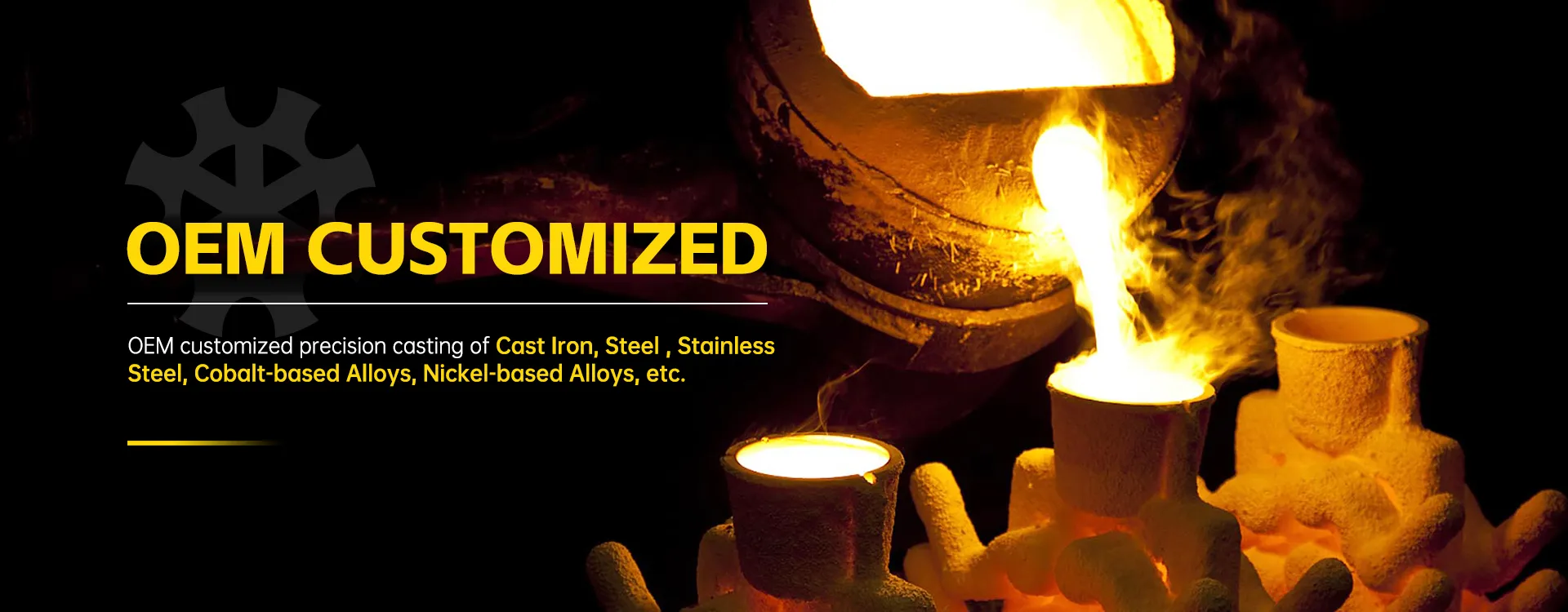
This is the point of no return. You've molded and debinded a fragile 'brown part'. Now, in the sintering furnace, the metal particles fuse and the true material properties emerge. This is where your choice of base material—stainless steel, tool steel, special alloy—faces its trial by fire. Atmosphere control is king. A tiny oxygen leak in a hydrogen-nitrogen atmosphere when sintering a chromium-containing steel like 17-4PH can decimate surface carbon and ruin corrosion resistance. We learned to run dummy parts before every critical batch to 'test' the furnace atmosphere, a cheap insurance policy.
The sintering cycle itself is a material-specific recipe. Ramp rates, hold temperatures, cooling speeds—they all dictate the final microstructure. For a project requiring a soft magnetic alloy (like Fe-50%Ni), the cooling rate from sintering temperature was critical to develop the desired magnetic permeability. Too fast, and we missed the property window. It took three furnace runs with subtle cooling tweaks to hit the spec. The 'material' on the purchase order was just Fe-50Ni. The functional material was created in that furnace.
Shrinkage is the other great variable, directly tied to the feedstock. We aim for isotropic shrinkage, but it's never perfectly uniform. For a precision gear component, we had to design the mold cavity based on an empirical shrinkage factor we'd developed for that specific 4140 alloy feedstock, not the vendor's generic 15-18% claim. Our factor was 16.7% ±0.3% in the critical plane. That precision came from measuring hundreds of sintered parts and correlating back. That's the kind of material knowledge that stays in a company's internal playbook.
Why Alloys Like Cobalt and Nickel Change the Game
Moving from common stainless steels into realms like cobalt-based alloys or nickel-based alloys for MIM is a step-change in difficulty and cost. These aren't just 'fancier steels'. Their sintering windows can be incredibly narrow. A cobalt-chromium-molybdenum alloy for biomedical use might sinter within a 20-degree Celsius window to achieve full density without grain growth. Miss it, and you get either residual porosity or embrittlement.
The binder removal for these high-performance alloys is also trickier. Their powders are often more reactive, so catalytic debinding (using nitric acid vapor, for instance) might be preferred over slower thermal methods to avoid surface contamination. This adds process complexity and cost. But the payoff is parts with properties nearing wrought material—think of jet engine fuel injector swirlers made via MIM from a nickel superalloy. The value is in the net-shape complexity, not just the material cost.
This is an area where deep foundry and machining experience becomes invaluable. A company with a long history in investment casting and machining special alloys, like Qingdao Qiangsenyuan Technology Co., Ltd. (QSY), brings a different perspective to MIM. They've been dealing with the metallurgy of special alloys for decades through their shell and investment casting operations. That ingrained knowledge about how these metals behave under heat, how they interact with atmospheres, and how they can be finished is a huge asset when venturing into molding them. They understand that the post-sintering state is just the starting blank for many parts, which will then need precise CNC machining to meet final tolerances on critical features. The MIM process and the material selection are designed with that subsequent machining step in mind.
The Machining Link: MIM Doesn't Always Mean 'Finished'
A common misconception is that MIM parts pop out of the furnace ready to use. For many, yes. But for high-precision applications, sintering is followed by secondary operations. This is critical for material selection. You might choose a pre-hardened grade, or one that will be heat-treated after sintering. But you also have to consider machinability. A sintered MIM part has a fine, uniform microstructure, but it's not always a dream to machine. It can be abrasive.
We had a case with a 440C stainless steel MIM part that needed a tapped hole. The part was fully dense and hard after sintering. Tapping it directly was chewing up tools. We had to adjust the sintering cycle to leave it in a slightly softer state for machining, then add a subsequent hardening heat treat. The 'material' process was thus: feedstock formulation -> molding -> debinding -> sintering (soft) -> CNC machining -> heat treatment -> final product. The material's journey wasn't over after the furnace.
This integrated view is key. It's why some of the most successful players aren't pure MIM shops. They are integrated manufacturers, like QSY, who combine processes. They can look at a drawing for a complex, high-alloy component and judge whether investment casting, MIM, or a hybrid approach is best based on geometry, material, and volume. Their 30 years in casting and machining mean they select MIM materials with a full understanding of the entire manufacturing chain, not just the molding and sintering steps. They know that the true cost of a material includes how it behaves in every subsequent operation.
Failures and the Lessons They Imprint
You don't learn materials from successes. You learn from the bins of scrap. Early on, we tried to run a low-alloy steel feedstock meant for automotive parts. The parts sintered fine, looked great. But in salt spray testing, they rusted in hours, while a traditionally machined part of the same grade lasted weeks. The culprit? Carbon loss during sintering due to an atmosphere not perfectly tuned for that particular powder's surface chemistry. The material 'grade' was correct, but the process had altered its effective composition. We had to switch to a powder engineered for MIM, with a different surface passivation, and tighten the furnace protocol. The spec sheet was useless if we didn't control the process that created the final material.
Another time, we explored using a MIM-able tungsten heavy alloy. The density was fantastic, but the feedstock was notoriously difficult to mold consistently. We spent months on gate and runner design, mold temperatures, injection parameters. We got functional parts, but the yield was never economically viable for the volume. We shelved it. The material was promising on paper, but the practical realities of transforming it from feedstock to reliable component killed the project. That's a crucial judgment call you only make by trying and failing.
So when I think about metal injection molding materials now, I don't just see a list of alloys. I see a cascade of decisions: powder shape and size, binder chemistry, powder loading, debind method, furnace atmosphere profile, possible heat treatment, and necessary secondary machining. The material is this entire chain. It's a process-defined entity. Getting it right means respecting every link, and that knowledge isn't bought—it's built part by part, failure by failure, over years. It's the difference between ordering a powder and engineering a component.