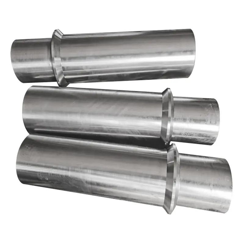
When most people hear 'metal roller,' they picture a simple, solid cylinder. In reality, that's where the first big misconception lies. The term covers a universe of components, from the basic conveyor idler to the heart of a rolling mill, and everything in between. Getting the application wrong at the spec stage is a costly mistake I've seen too often. It's not just about diameter and length; it's about the interplay of material, surface finish, thermal dynamics, and load profiles that separates a part that lasts from one that fails prematurely.
The Core: Material and Process Decisions
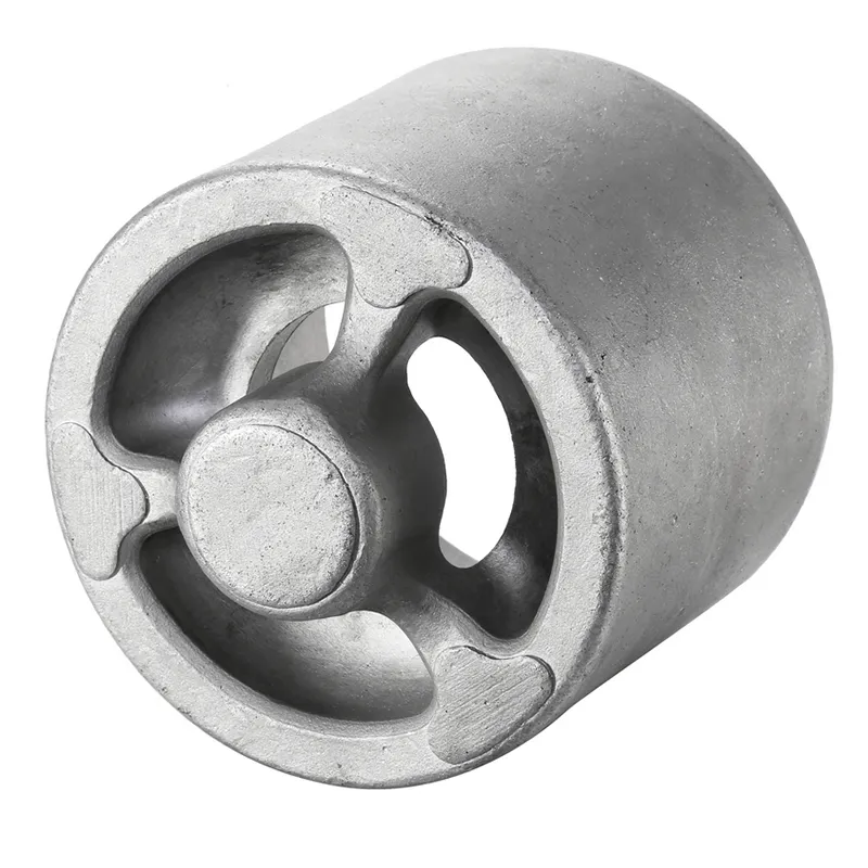
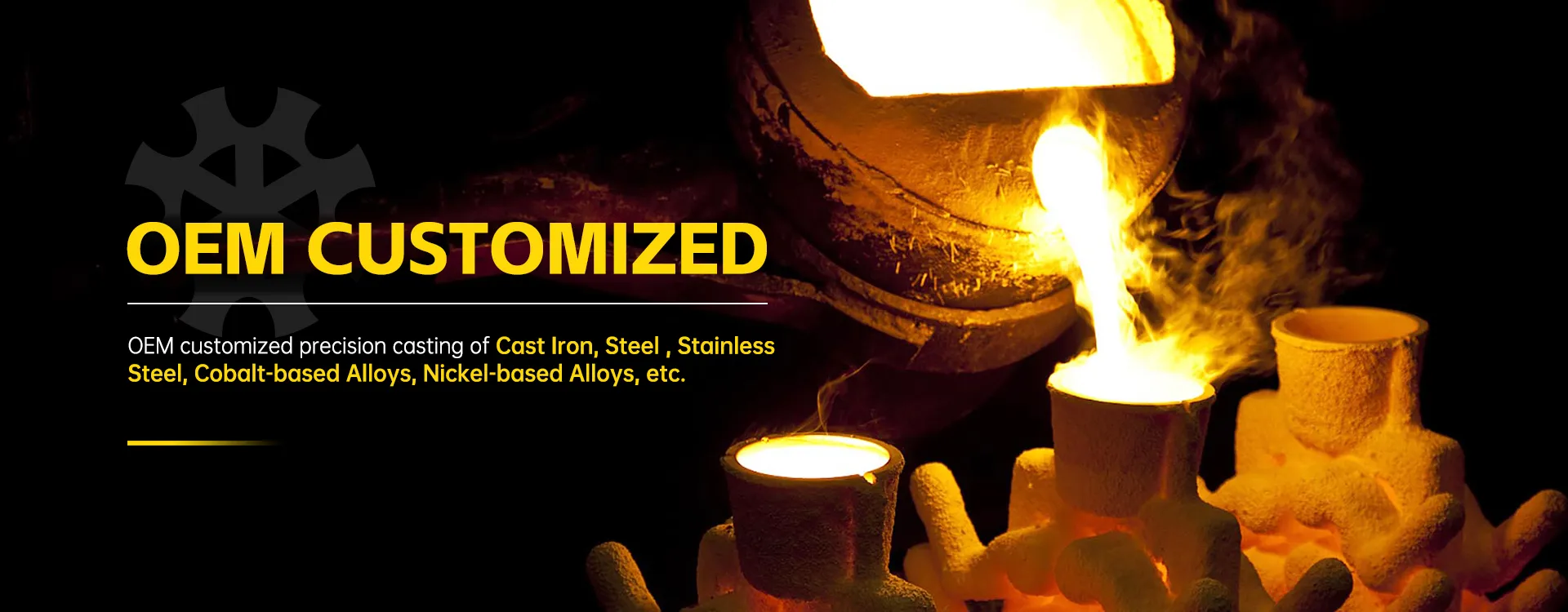
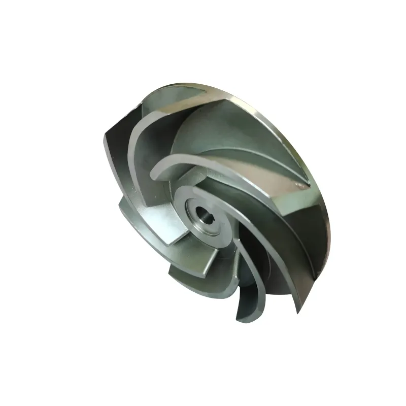
Choosing the base material is the first real fork in the road. For general conveying under moderate loads, a hardened carbon steel might do. But introduce heat, corrosion, or extreme pressure, and you're in alloy territory. This is where foundries with deep material experience become critical. I've worked with Qingdao Qiangsenyuan Technology (QSY) on several projects precisely because of their 30-year background in casting. They don't just pour metal; they understand how different alloys behave under stress. For a high-temperature calendering roller, we opted for a nickel-based alloy through their investment casting process. The alternative—fabricating from a solid bar—would have been prohibitively expensive and wasteful.
The casting method itself dictates a lot. Shell mold casting is excellent for larger, relatively simpler geometries in iron or steel, giving a good balance of cost and surface integrity. But for the complex internal cooling channels we needed in a printing industry roller, investment casting was the only way to achieve the near-net-shape precision without extensive post-cast machining. The as-cast surface from a good investment process can sometimes reduce the final grinding time significantly.
One failure that sticks with me was an early attempt to use a standard stainless steel (304) for a roller in a mildly acidic washdown environment. We figured it was 'stainless,' so it should hold up. It pitted within six months. The issue wasn't the grade selection per se, but the post-casting heat treatment and passivation. The supplier at the time skipped proper passivation, leaving the surface vulnerable. Now, we always specify not just the alloy, like 316L or 17-4 PH, but also the exact heat treat protocol and surface passivation requirements. A company like QSY, listed at tsingtaocnc.com, gets this; their expertise in special alloys means they're thinking about these post-processing steps from the moment the alloy is selected.
Precision is in the Finish: The Machining Dance
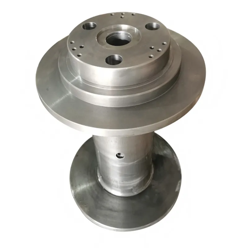
Casting gets you 80% there. The final 20%—dimensional accuracy, concentricity, and surface finish—is where the machining takes over. This is the make-or-break phase. A roller can be perfectly cast from a superb alloy, but if it's machined off-center or with inconsistent wall thickness, it will vibrate, cause uneven wear, and ruin the product it's processing.
We lean heavily on CNC machining for this. For drive rollers, the tolerances on the bearing journals are often within a few hundredths of a millimeter. The challenge is holding these tolerances while managing the residual stress in the metal. A heavy cut in one pass can induce stress that warps the part later. It's a slower, more methodical process of roughing and finishing. I recall a large-diameter paper roller where we had to account for the part's own deflection during machining. We used live steady rests and adjusted cutting parameters in real-time based on feedback from the machinist—something that requires an operator who understands the material, not just the machine.
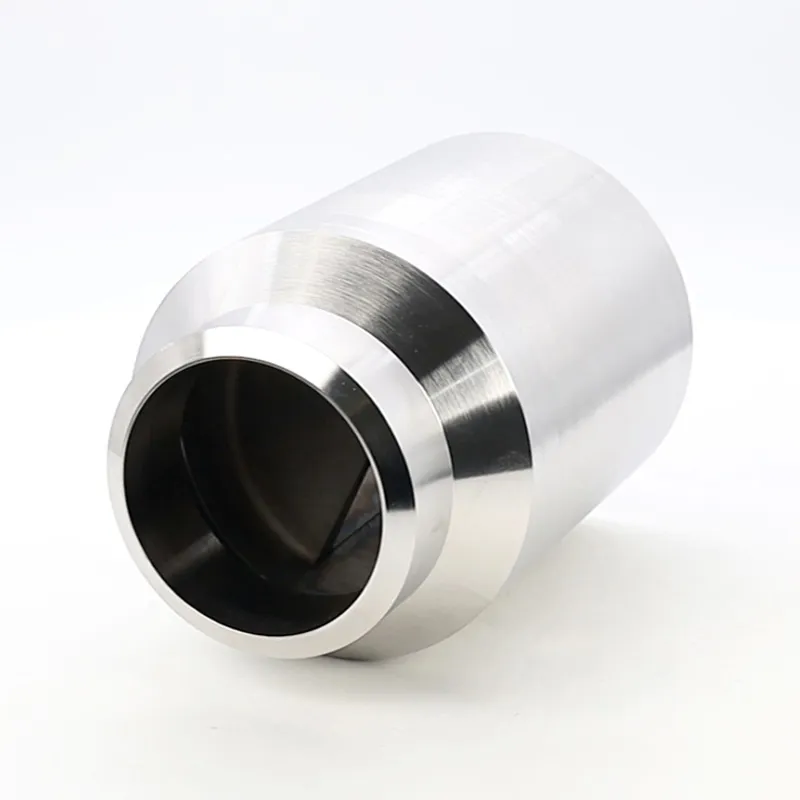
The surface finish requirement is another layer. A mirror finish for a film laminator roller is achieved through progressive grinding and polishing, often with diamond abrasives. But 'mirror finish' is vague. We specify Ra values (roughness average). An Ra of 0.2 micrometers feels smooth, but for some high-end applications, we need to get down to 0.05. Achieving this on a long roller requires a perfectly straight bed and a meticulous process. Any tiny imperfection in the underlying casting will telegraph through. That's why the partnership between the foundry and the machine shop is so vital. When they're under one roof, like at QSY where casting and CNC machining are integrated, the machinists can feed back to the foundry about subsurface porosity or hardness variations, creating a tighter feedback loop for quality.
Application Nightmares and Real-World Fixes
Textbook specs meet factory floor reality. A classic issue is thermal expansion. We designed a heated roller for a plastic extrusion line, calculating the expansion based on the alloy's coefficient. What we didn't fully account for was the temperature gradient across the face if the internal heating element failed on one side. The differential expansion caused a slight bow, enough to create a thickness variation in the plastic sheet. The fix wasn't to re-make the roller, but to redesign the heating cartridge layout and add more temperature sensors along the length for better control.
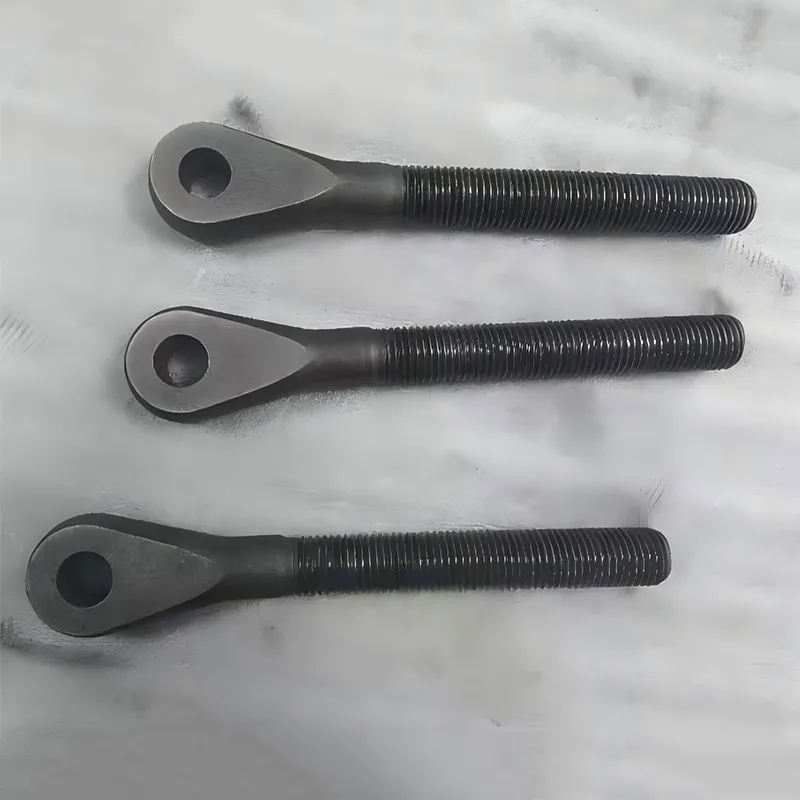
Another common headache is bearing seat fretting. On a high-speed roller, even microscopic movement between the roller's journal and the inner bearing race can cause fretting corrosion, which locks up the bearing. The solution often involves specifying a slightly tighter fit and sometimes using a specialty anti-fretting coating on the journal. It's a small detail that never appears in initial CAD models but becomes a major reliability issue.
Then there's balance. Dynamic balancing is a given for anything that rotates at speed. But static balance matters too, especially for large, slow-moving rollers. We had a wide fabric guide roller that seemed fine. But at its operational speed, an imbalance of just a few grams at the ends created a whip that damaged the fabric edges. The lesson: always specify the balance grade (e.g., G2.5 at operating RPM) and the correction planes. Don't assume the shop knows; spell it out.
When Standard Isn't Enough: The Custom Geometry
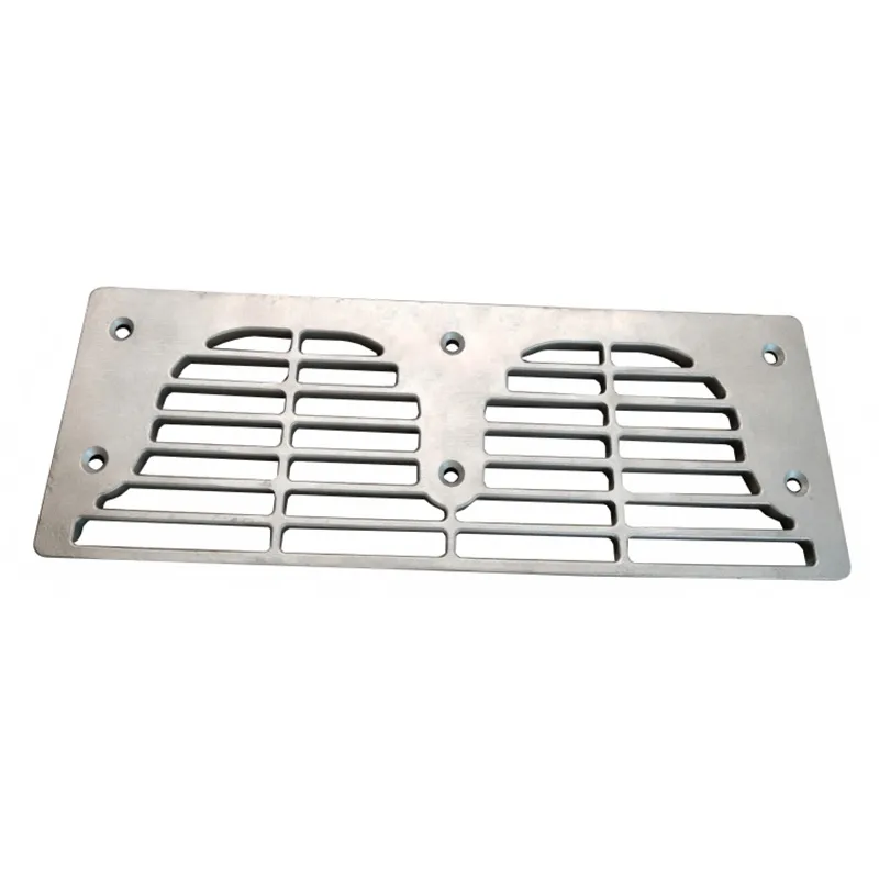
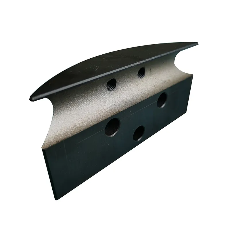
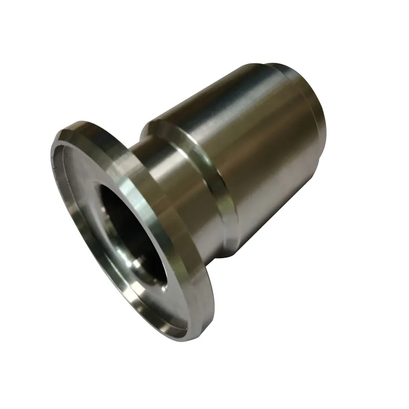
Most discussions focus on straight cylinders. But some of the most challenging projects involve custom profiles. Grooved rollers, crowned rollers (barrel-shaped), or rollers with helical patterns for web guiding. Each presents unique manufacturing hurdles. A crowned roller, for instance, requires precise CNC turning with a programmed curve. The crown measurement—the difference between the center and end diameters—might only be a few tenths of a millimeter over a two-meter length. Programming and verifying that takes skill.
For a grooved roller used in texturing, the sharpness and consistency of the groove root radius are critical. Using a standard cutting tool will leave a radius. If the design calls for a sharp corner, you often need to specify EDM (Electrical Discharge Machining) after initial turning, which adds cost and time. It's a trade-off that needs to be hashed out in the design review. Is that sharp corner functionally necessary, or is it just on the drawing because no one questioned it?
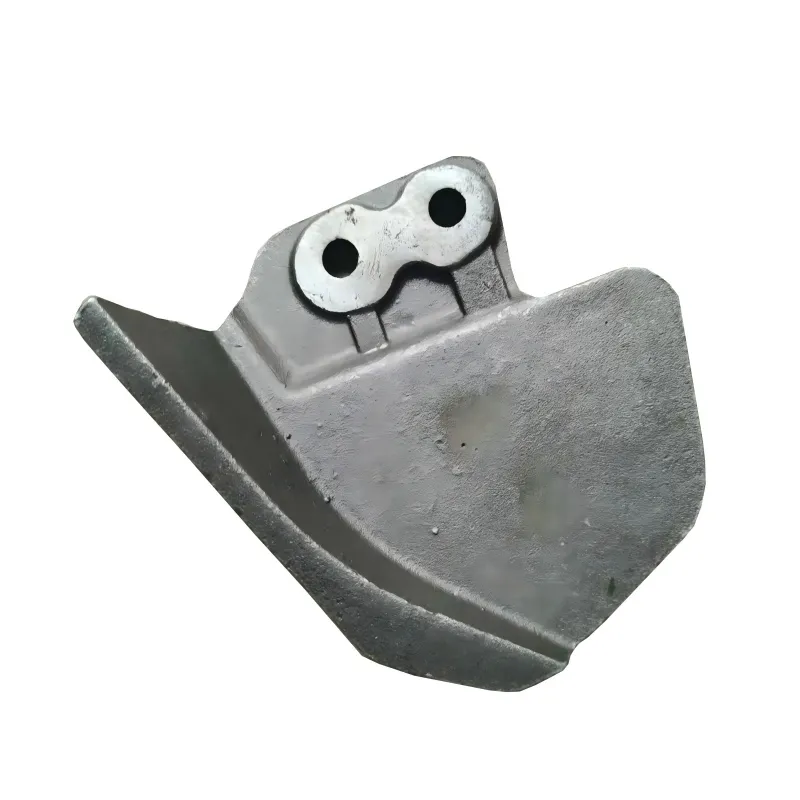
We once needed a large roller with a series of shallow, tapered recesses along its length—a kind of negative pattern. Machining it from solid would have been a nightmare of tool access and time. We worked with the engineering team at QSY to cast the basic recess pattern into the part using their shell mold process, which left minimal stock for the final CNC machining to clean up. It saved about 30% in machining hours and produced a stronger part because the grain flow of the metal followed the contour. That's the kind of value you get from a supplier who thinks in both casting and machining terms.
The Unseen Factor: Maintenance and Lifecycle
A well-made metal roller should be designed for its entire lifecycle, not just its first installation. This means considering how it will be maintained. Are there threaded holes for pullers? Is the surface coating or plating reparable? For a chrome-plated roller, can it be stripped and re-plated after years of wear, or is the base material incompatible with a second plating cycle?
Documentation is part of this. A reliable supplier provides material certifications, heat treat charts, and inspection reports. When you need an identical replacement roller five years later, you need to know exactly what you had. I keep a full dossier on critical rollers, and the best suppliers, like the one I've referenced, provide this data without being asked. It's a sign they stand behind their process.
Finally, failure analysis. When a roller does fail—and they all do eventually—the way it fails tells a story. Spalling on the bearing journal points to an overload or fit issue. Thermal checking on the surface indicates cooling problems. A catastrophic crack might stem from a subsurface casting flaw. Taking the time to do a proper post-mortem on a failed roller informs the design of the next one, closing the loop. It turns a breakdown into a learning point, which is the real mark of practical, hands-on experience in this field.