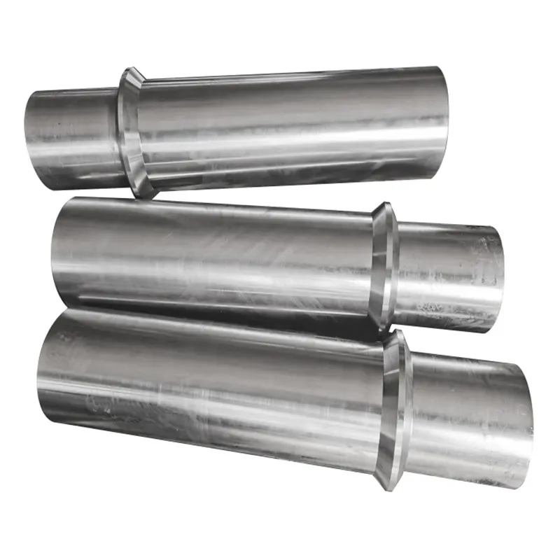
When most people hear 'metal shaft', they picture a simple, solid rod. In practice, that's where the first major misconception lies. It's never just a rod. It's a load-bearing, torque-transmitting, often precision-balanced component whose failure can halt an entire assembly line. I've seen too many projects treat it as a commodity item, leading to costly rework. The real challenge isn't in making it; it's in specifying it correctly from the outset—material, tolerance, finish, and the often-overlooked aspect of residual stress from machining.
Material Selection is More Than a Grade
Picking 4140 steel or 304 stainless because it's on a standard list is a start, but it's a naive one. The operating environment dictates everything. I recall a project for a marine pump where the initial spec called for a standard 316 stainless metal shaft. It passed initial tests but failed in the field within months. The issue? Not general corrosion, but crevice corrosion and stress corrosion cracking at the keyway under cyclic loading in chlorinated water. We had to switch to a duplex stainless grade with better chloride resistance and adjust the machining process to induce compressive stress on the surface. The takeaway? The alloy number is just the entry ticket.
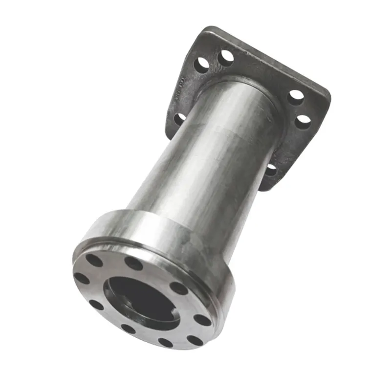
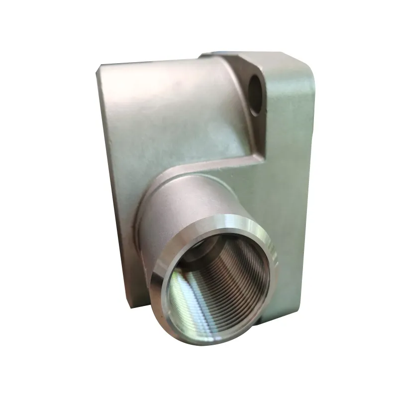
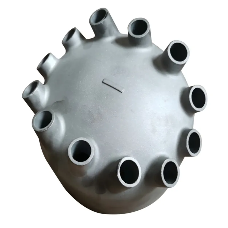
This is where long-term suppliers with foundry and machining under one roof show their value. A company like Qingdao Qiangsenyuan Technology Co., Ltd.(QSY), with their three decades in casting and machining, understands this interplay. They don't just machine a billet; they can start from a shell or investment casting, which can be crucial for complex shaft geometries with flanges or unusual profiles. Controlling the material's journey from molten metal to finished part reduces hidden risks.
For high-wear applications, like in agitators for abrasive slurries, we've moved beyond through-hardening. Surface treatments like induction hardening on a carbon steel core or even applying Stellite (a cobalt-based alloy) weld overlays on specific wear zones become necessary. It's a cost-benefit analysis: a more expensive metal shaft that lasts three years versus a cheaper one replaced annually. The total cost of ownership rarely favors the cheap option.
The Machining Finish: Where Specs Meet Reality
A drawing might call for a 0.8 Ra surface finish. Achieving it is one thing; achieving it consistently on a production run of 500 shafts is another. The devil is in the setup, tool wear, and coolant management. A mirror finish might look impressive, but for a shaft running in a plain bearing, you actually need a certain cross-hatch pattern for oil retention. Too smooth, and you risk galling.
I learned this the hard way on a high-speed packaging machine. The shafts were beautifully polished to a 0.4 Ra. They overheated and seized within a week. The problem wasn't the finish value itself, but the lack of defined lubrication grooves and the wrong surface texture direction. We had to re-machine all units, adding a specific plateau honing process. Now, I always specify not just the Ra, but also the Rz and the lay pattern (circumferential, axial, or cross-hatched) on the drawing. Most generic machine shops will ignore this unless you drill it into them.
CNC machining centers, like those you'd find at a specialized processor's facility (their site at tsingtaocnc.com details their capabilities), are essential for repeatability. But the programmer's knowledge is key. How they sequence operations—roughing, semi-finishing, finishing—affects heat input and dimensional stability. A heavy cut left for the final pass can distort the part after it's unclamped. It's a subtle art masked as a science.
Balancing Act: Not Just for Turbines
Everyone knows turbine shafts need dynamic balancing. But what about a fan shaft running at 3000 RPM? Or a conveyor drive shaft that's 3 meters long? The need for balancing is grossly underestimated. An unbalanced metal shaft creates vibration, leading to premature bearing failure, seal wear, and noise. For anything rotating above about 1000 RPM, I now mandate a balancing specification, even if it's just a static balance for slower, rigid rotors.
The method matters. We usually specify G2.5 balance quality grade for most industrial machinery shafts. But achieving it requires careful planning. You need material uniformity (hence the importance of a good casting or forged blank), symmetrical machining, and designated locations for adding or removing weight. I've seen shops drill random holes to balance a shaft, severely compromising its fatigue strength. The correct way is to have machined pads or flanges designed in from the start for balance weights.
For a long, slender shaft, the story gets more complex. It might be straight and balanced when cold and static, but under its own weight and thermal expansion at operating speed, it can sag and induce imbalance. Sometimes, you're not balancing the shaft alone, but the entire rotor assembly. This requires collaboration with the machinist to provide balancing journals and understand the assembly sequence.
Tolerances and Fits: The Language of Assembly
A shaft diameter of 50mm. What does that mean? Nothing without a tolerance. A h7 fit for a bearing seat, a k6 for a gear press fit, a f7 for a seal running surface. Getting these wrong is the fastest route to assembly failure. I once received a batch of shafts where the bearing journals were machined to a g6 tolerance instead of h7. It was a better (tighter) tolerance, but it meant the bearings, which were already a tight press fit, became nearly impossible to install without a hydraulic press, risking damage.
The other critical dimension is geometric tolerance: straightness, cylindricity, and concentricity. A shaft can have every diameter in spec but have a 0.1mm bend over its length. This will cause runout, vibration, and uneven wear. For critical shafts, we now always specify a straightness callout, often over a 500mm span. Checking this requires proper V-blocks and a dial indicator, not just a pair of calipers.
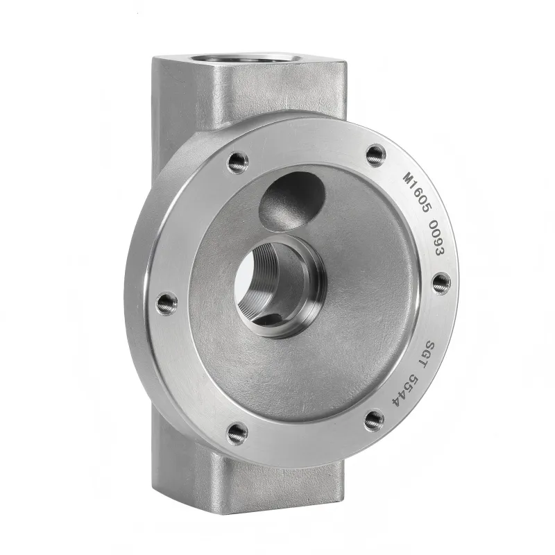
This precision is where integrated services pay off. A company that handles both the casting for near-net-shape and the final CNC machining, like QSY, has better control over this. They can machine critical datum surfaces on the casting first, then use those to hold the part for subsequent operations, ensuring concentricity and positional accuracy from the start. Trying to clamp on a rough-cast surface for finish machining is a recipe for inconsistency.
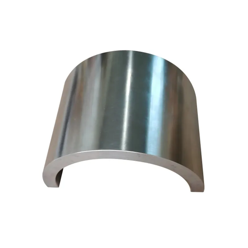
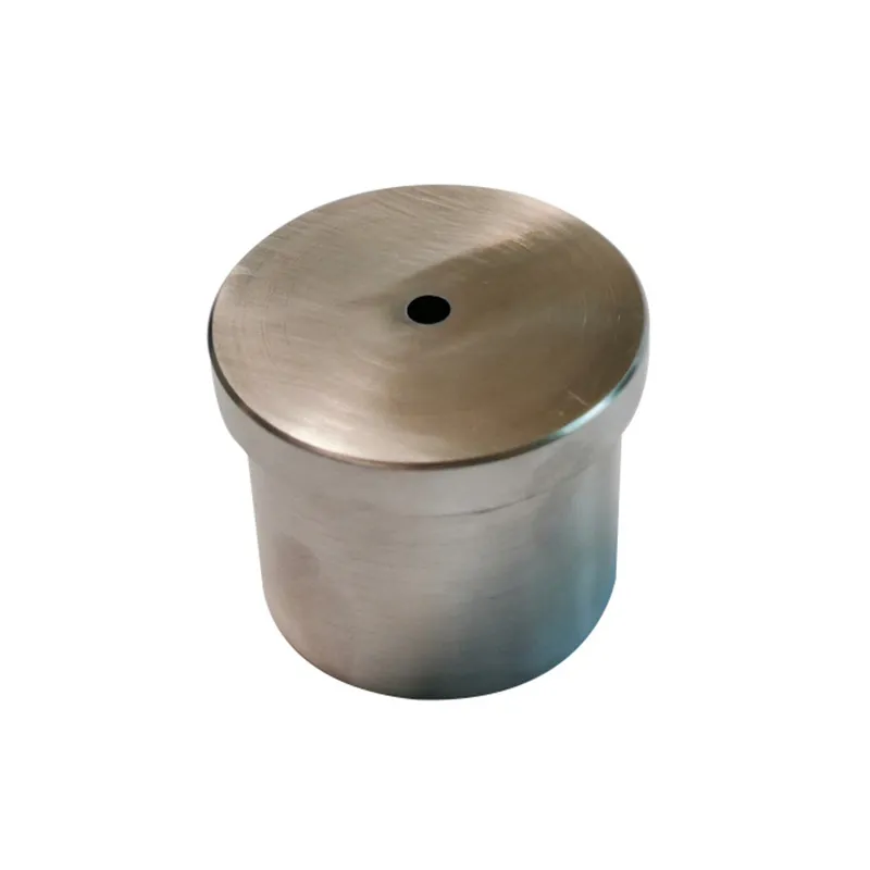
When a Shaft Isn't Solid: Hollow Shafts and Internal Features
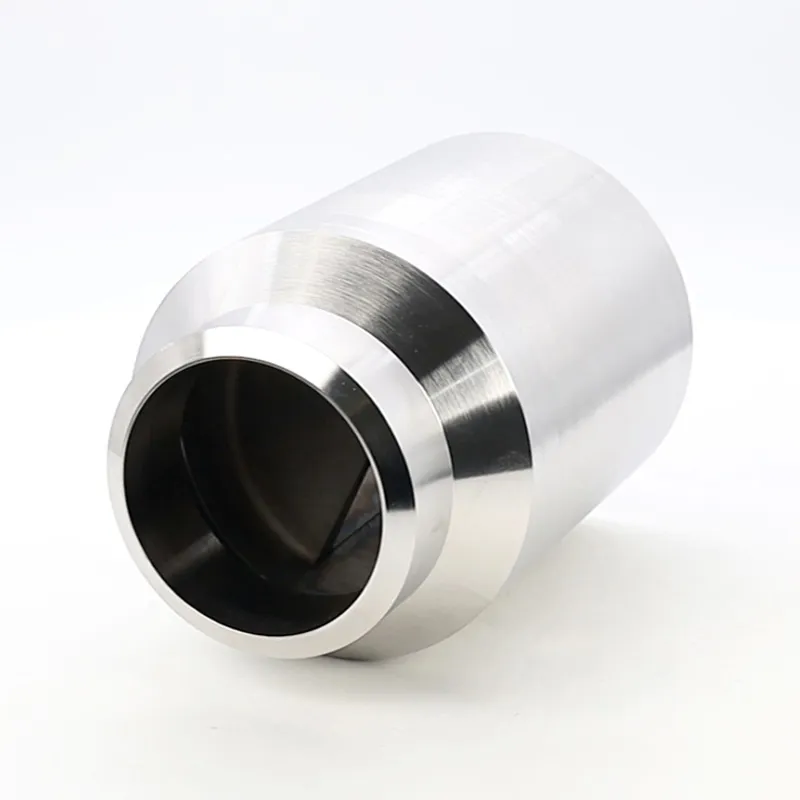
Not all shafts are solid bars. Hollow shafts are critical for weight reduction (in aerospace or automotive applications) or for serving as conduits for coolant, hydraulic fluid, or wiring. This introduces a new set of challenges. Machining a deep, small-diameter bore with tight straightness and surface finish requirements is a specialized task. Tool deflection, chip evacuation, and coolant delivery become major headaches.
We designed a hollow metal shaft for a rotary union application. The internal bore needed a 1.6 Ra finish and precise concentricity with the outer bearing journals. Our first supplier struggled with boring bar chatter, leaving a terrible finish. The solution came from a machinist who suggested using a single-point boring bar with a specific geometry and a high-pressure through-tool coolant system to break chips and dampen vibration. It worked, but it was a process developed through trial and error, not a standard operation.
For such complex internal machining, processes like gun drilling are often used. It's a slow, precise operation. This is a good example of where you need a shop with the right specialized equipment and the patience to dial in the process. It's not a high-volume, quick-turnaround job. You're paying for expertise and capability, not just machine time.
The Forgotten Factor: Residual Stresses and Long-Term Stability
This might be the most overlooked aspect in standard metal shaft manufacturing. Machining, especially aggressive turning or grinding, introduces residual stresses into the surface layer. These stresses can relax over time, causing the shaft to warp slightly. For a standard conveyor shaft, it might not matter. For a precision spindle in a machine tool, it's catastrophic.
We had a batch of grinding machine spindles that passed all initial QC checks. After sitting in storage for six months, about 30% of them showed measurable runout. The culprit? Residual stress from grinding, combined with a material (a tool steel) that was not sufficiently stress-relieved prior to final machining. The fix was to implement a low-temperature thermal aging process (sometimes called artificial aging) after finish grinding to accelerate stress relief before final inspection.
Controlling this requires a holistic manufacturing approach. Starting with a properly heat-treated blank (annealed, normalized, or quenched and tempered) is step one. Then, machining should be done in stages with stress relief in between for critical parts. A full-service provider that manages the entire chain—from sourcing the right alloy, to casting/forging, heat treatment, and final machining—is best positioned to control these variables. It's the difference between making a part that works on the day it's made and one that works reliably for years.