You see a lot of talk about straightener shafts in wire and bar processing, but the real story isn't in the catalog specs. It's in the grime, the heat cycles, and the subtle deflection you only notice after running 50 tons of high-carbon steel. Everyone focuses on hardness, but if the core isn't right, it's just a fancy, expensive stick waiting to cause a line shutdown.
The Core Misconception: Hardness Isn't Everything
When most shops or even some OEMs spec a straightener shaft, the first data point is always surface hardness. HRC 58, 60, maybe higher. Sure, you need that wear resistance where the rolls contact. But I've pulled apart shafts that met the hardness spec yet failed prematurely. The failure wasn't on the surface; it was a fatigue crack initiating about 5mm below. The material core had poor toughness. Under the cyclic bending loads of straightening, especially with inconsistent feedstock, that's where it gives.
This is where material selection gets real. It's not just stainless steel or alloy steel. For a shaft that sees high dynamic stress, you need a through-hardening grade with a good balance. Something like 4140 or 4340, properly heat-treated to get a consistent martensitic structure through the cross-section. I've seen outfits try to save cost with a medium carbon steel and just induction harden the surface. It works, until it doesn't—and the break is catastrophic, not gradual.
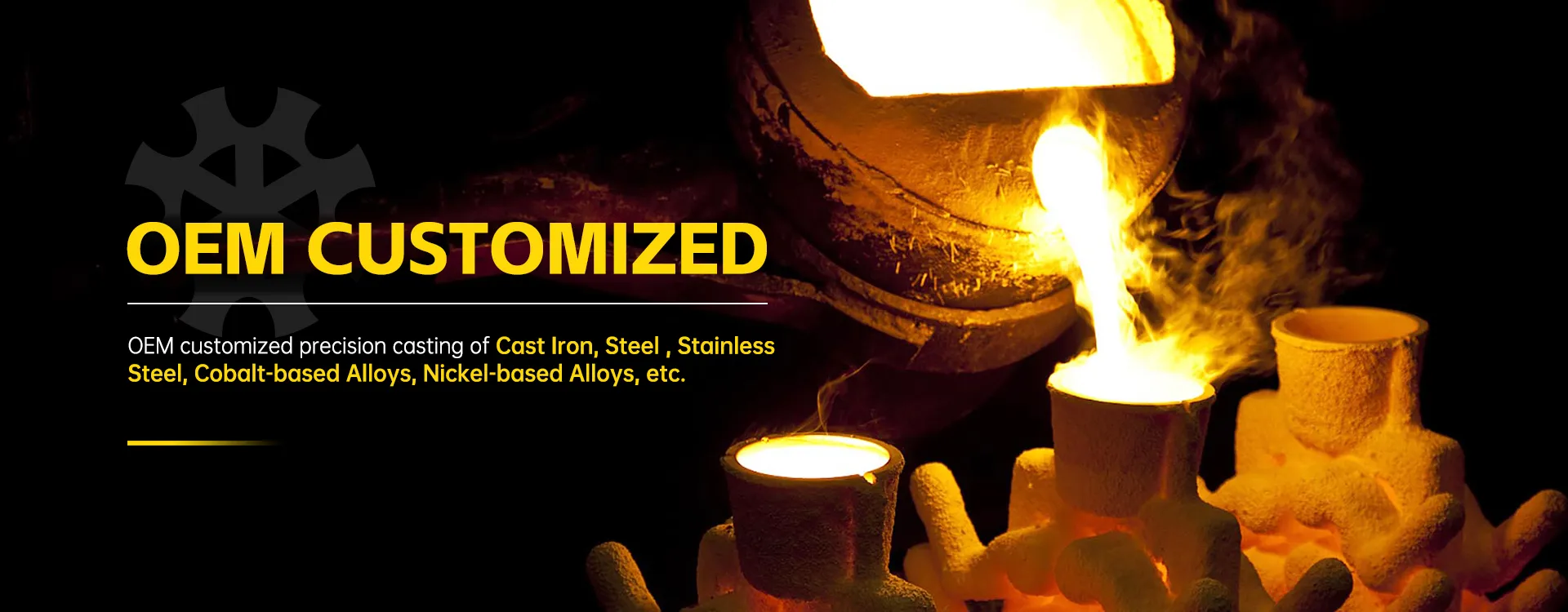
We had a case with a client running a high-speed wire line for spring steel. They were eating through shafts every 8 months. The specs looked fine on paper. We got one of their failed units, did a metallurgical analysis, and found a significant variance in core microstructure—signs of improper quenching. The surface was hard, but the core was essentially a different, weaker material. The fix wasn't a harder material, but a more controlled process. This is the kind of nuance companies like Qingdao Qiangsenyuan Technology Co., Ltd. (QSY) understand from their decades in casting and machining. They're not just cutting metal; they're managing the entire material transformation, which is critical for a stressed component like this.
Geometry & Tolerances: Where Theory Meets the Machine
The drawing calls for a straightness tolerance of, say, 0.05mm per meter. Achievable on a good lathe or grinder. But that's in a climate-controlled inspection room. The real test is when the shaft is bolted into the straightener frame, pre-loaded, and heated to 60°C by friction and ambient plant heat. Does it stay straight? Or does it take a slight set?
The diameter tolerances for the bearing journals are another classic pitfall. Too tight a fit, and you risk galling during installation or seizure from thermal expansion. Too loose, and you get fretting wear, vibration, and eventually, wobble that ruins the straightening accuracy. I prefer a controlled transition, sometimes even specifying a slight lead-in chamfer that isn't always on the standard print, to make field maintenance possible without a hydraulic press and a prayer.
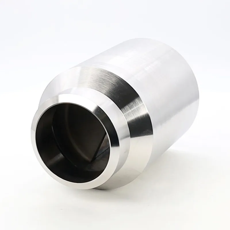
Then there's the finish. The journals need a fine grind, often to 0.4 Ra or better. But the sections between the roll seats? You might see machined grooves or even a rough-turned finish. There's a reason. That texture can actually help retain lubricant and dissipate heat better than a perfectly smooth surface. It's a small, practical detail you learn from seeing these parts in service, not just from designing them.
The Manufacturing Dance: Casting vs. Machining from Bar
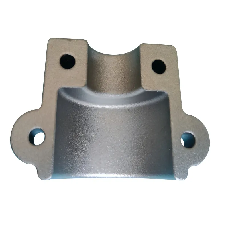
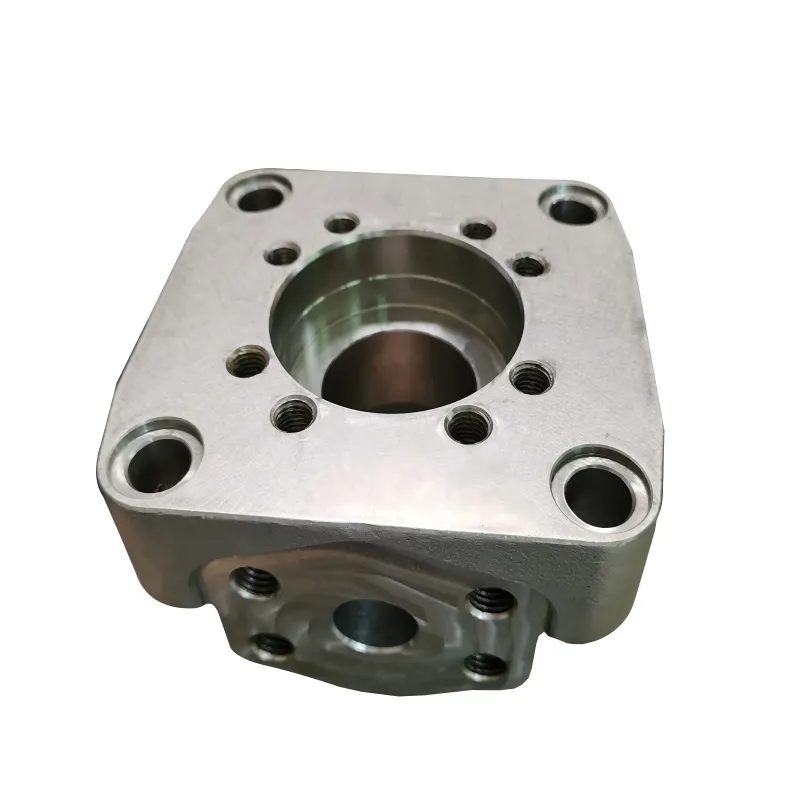
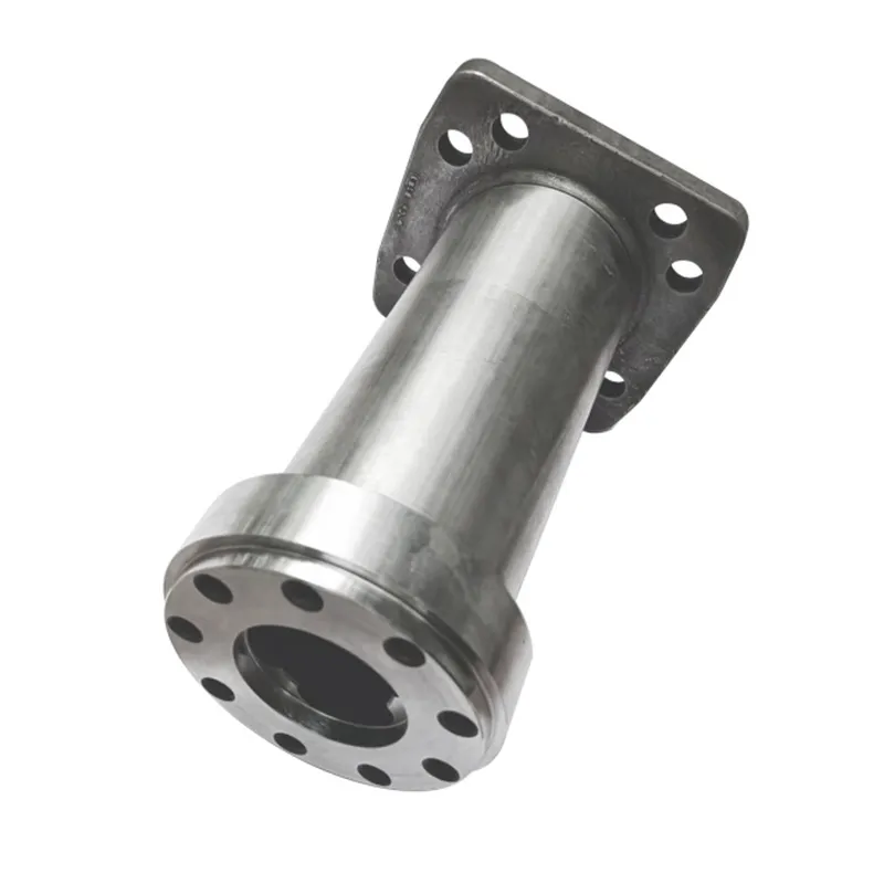
For standard sizes, a straightener shaft is often machined from a forged or rolled bar stock. It's predictable. But for larger diameters, complex integral features (like flanges or unusual counterweight shapes), or when material yield is a big cost factor, casting becomes interesting. This is where a foundry's skill is paramount.
A cast shaft needs a flawless process to avoid internal shrinkage cavities or inclusions that become stress risers. The advantage is you can get closer to net shape, saving a lot of machining time on waste material. The downside is you absolutely must have rigorous non-destructive testing (NDT). We did a trial run years ago on a large-diameter shaft for a copper rod line. We went with a casting to integrate the bearing housing. The first article passed all dimensional checks but failed an ultrasonic test—a small, clustered porosity zone right in a high-shear area. Had to scrap it. The second attempt, with revised gating and riser design from the foundry, was solid.
This is the kind of capability you look for in a supplier. A company like QSY, with its long history in shell mold casting and investment casting, can navigate these choices. Shell mold is great for steel and iron parts with good surface finish and dimensional accuracy, while investment casting is for the more complex, alloy-heavy designs. They can assess whether a shaft is better made from a solid bar on their CNC machining centers or if a casting route is more efficient, and they have the metallurgical knowledge to specify the right nickel-based alloys or cobalt-based alloys for extreme wear or corrosion environments.
Failure Modes: The Stories Shafts Tell
You learn more from a broken part than a perfect one. The fracture surface is a history book. A clean, single-plane fracture with beach marks radiating from one point? Classic fatigue failure. Starts at a stress concentrator—maybe a sharp corner at the end of a keyway that wasn't radiused properly, or a tool mark that acted like a micro-crack.
I recall a shaft that kept shearing the Woodruff key. Everyone kept upgrading the key material. Finally, we looked at the keyway itself. It was machined with a standard end mill, leaving a sharp, square bottom. The crack was initiating there. The solution was a simple instruction to the machinist: Put a radius in that keyway bottom, as large as the design allows. Never had another failure. It's a five-minute machining detail that most CAD models don't even show.
Another common, subtle failure is torsional wind-up. On straighteners with driven rolls, the shaft transmits torque. If the diameter is under-designed for the torsional load, you get angular deflection. This doesn't break the shaft immediately; it just makes the straightening pattern inconsistent and ruins product quality. You might chase the problem for weeks, adjusting roll pressures, before you think to check if the shaft itself is twisting under load.
Integration & The Feel of a Good Shaft
Ultimately, a straightener shaft isn't an island. It's part of a system with bearings, housings, rolls, and the machine frame. The best shaft can be let down by poor alignment during installation. We always stress the installation procedure: use alignment lasers, not a spirit level. Check the runout at multiple points along the shaft's length once it's seated in its bearings, not just on the bench.
There's also an almost intangible feel to a well-made shaft. The balance. When you rotate it on steady rests before installation, it should turn smoothly without heavy spots. The surface should be clean, without tooling witness lines that you can catch a fingernail on. The weight should feel appropriate for its size and material—a sign of consistent density, especially in cast versions.
Suppliers that get this are the ones who've been on the factory floor themselves. They know their part has to work in a dirty, vibrating, hot environment. It's not just a drawing to them. When you work with a partner that offers both the casting expertise for material integrity and the precision CNC machining for the final fit and function—like the integrated service you'd find at a firm with QSY's profile—you're not just buying a component. You're buying a chunk of reliability. That's what keeps a processing line running, shift after shift. The goal is for the shaft to be the last thing the maintenance crew ever has to think about.