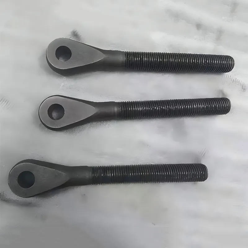
Shell moulding casting delivers precision, repeatability, and surface finish unmatched by conventional sand casting—especially for medium-complexity, high-volume components like hydraulic valve bodies, pump housings, and winch shafts. We’ve produced over 12,000 shell-moulded iron and steel castings in the past three years alone—most under ±0.15 mm dimensional tolerance and Ra 3.2 µm as-cast surface. This isn’t theoretical. It’s what happens when you combine phenolic resin chemistry, controlled core-box temperature, and real-time shell thickness monitoring on the shop floor.
Step 1: Pattern Preparation — Precision Starts With the Master
We use hardened steel or aluminum patterns—never wood or low-melt alloys—for shell moulding. Why? Because pattern life directly controls cost per part at volumes above 500 units. Our patterns include precise draft angles (0.5°–1.5°), vent grooves no narrower than 0.8 mm, and integrated gating features that eliminate manual runner cutting. Each pattern undergoes CMM verification against customer GD&T before first use. Some clients send us 3D-printed prototypes for functional testing—but we never cast from them. Thermal expansion mismatch between printed resin and molten metal causes unpredictable warpage in the shell.
Step 2: Shell Formation — Heat, Resin, and Timing Are Non-Negotiable
The pattern is preheated to 220–250°C. Too cold? Incomplete resin curing. Too hot? Premature decomposition and gas defects. We coat it with fine silica sand (40–100 mesh) mixed with 2.5–5% thermosetting phenolic resin. The coated pattern rotates inside a dump box for 10–20 seconds—just long enough for a uniform 6–12 mm shell to form. Then it’s inverted and baked at 380–420°C for 2–4 minutes. That final bake crosslinks the resin fully. Skip it, and the shell crumbles during mold assembly. We monitor oven temperature every 90 seconds using calibrated thermocouples—not ambient readings.
Step 3: Mold Assembly — Alignment Dictates Dimensional Stability
Two half-shells are glued with heat-activated phenolic adhesive or mechanically pinned. No clay, no nails, no tape. Misalignment of even 0.3 mm shows up as flash on pressure-bearing surfaces—like cylinder housing flanges or valve seat lands. For asymmetrical parts, we use dowel pins with ±0.01 mm positional tolerance. Before pouring, each assembled mold passes through an optical alignment station. If the gap between halves exceeds 0.1 mm at any point, it’s scrapped—not reworked. Reassembly introduces cumulative error.
Step 4: Pouring and Solidification — Controlled Flow Prevents Turbulence
- Pour temperature is held within ±15°C of optimal range—e.g., 1,420–1,450°C for ASTM A126 Class B gray iron
- Metal enters via bottom gating to minimize oxide entrapment
- Shakeout occurs 15–25 minutes post-pour—timed per section thickness, not clock time
- No forced cooling. Rapid quenching cracks shells and induces residual stress in thin-walled housings
We once poured 48 identical piston pump cylinder housings in one heat. Six showed micro-shrink in the valve port recess. Root cause? A 7°C drop in ladle temperature during the last 12 pours. Now we log pour temp for every single mold—and reject any batch where variation exceeds ±10°C.
Step 5: Post-Casting Handling — Where Surface Integrity Is Won or Lost
Shell moulding gives near-net shape—but not net shape. Critical sealing surfaces still require CNC machining. That’s why we integrate casting and machining under one roof. Our iron castings go straight from shakeout to horizontal machining centers—no intermediate storage. Why? Moisture absorption into porous surfaces causes hydrogen pinholes during subsequent heat treatment. We also avoid shot blasting on parts destined for AMS 5387-compatible applications; angular media damages the near-surface grain structure needed for fatigue resistance in cobalt-alloy pump components.
Shell moulding casting excels where sand casting lacks consistency and investment casting strains budgets—typically for parts weighing 0.5 kg to 50 kg, annual volumes from 1,000 to 50,000 units, and materials including ductile iron, carbon steel, stainless steels, and nickel-resist alloys. At QINGDAO QIANGSENYUAN TECHNOLOGY CO., LTD., we treat shell moulding not as a standalone process but as one node in a verified casting-machining-finishing loop. Every shell-moulded component we ship carries full material traceability, CMM-certified dimensions, and a documented thermal history—from pattern bake to final stress relief. That’s how pressure valves survive 20,000 PSI cycles. That’s how winch center shaft rollers maintain runout under 0.02 mm after 10,000 hours. Precision isn’t achieved in one step. It’s locked in—step by step.