Summary: Learn when precision prototype machining is appropriate, how to select materials and tolerances, prepare an RFQ, and compare machining with casting.
Precision prototype machining helps engineers evaluate metal parts before committing to production. By machining a prototype from a selected material, a development team can check assembly fit, critical dimensions, functional features, and manufacturing feasibility.
The value of a prototype depends on what it is intended to prove. A part that fits an assembly may still be unsuitable for mechanical testing if its material differs from the intended production material. Likewise, a dimensionally accurate prototype may not fully represent a final component made through casting, heat treatment, or another manufacturing process.
This guide explains when precision prototype machining is appropriate, how to select materials and define critical tolerances, what to include in a request for quotation (RFQ), and when casting followed by CNC machining may be a better option.
1. What Is Precision Prototype Machining?
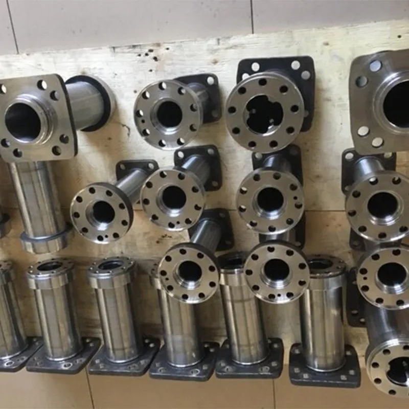
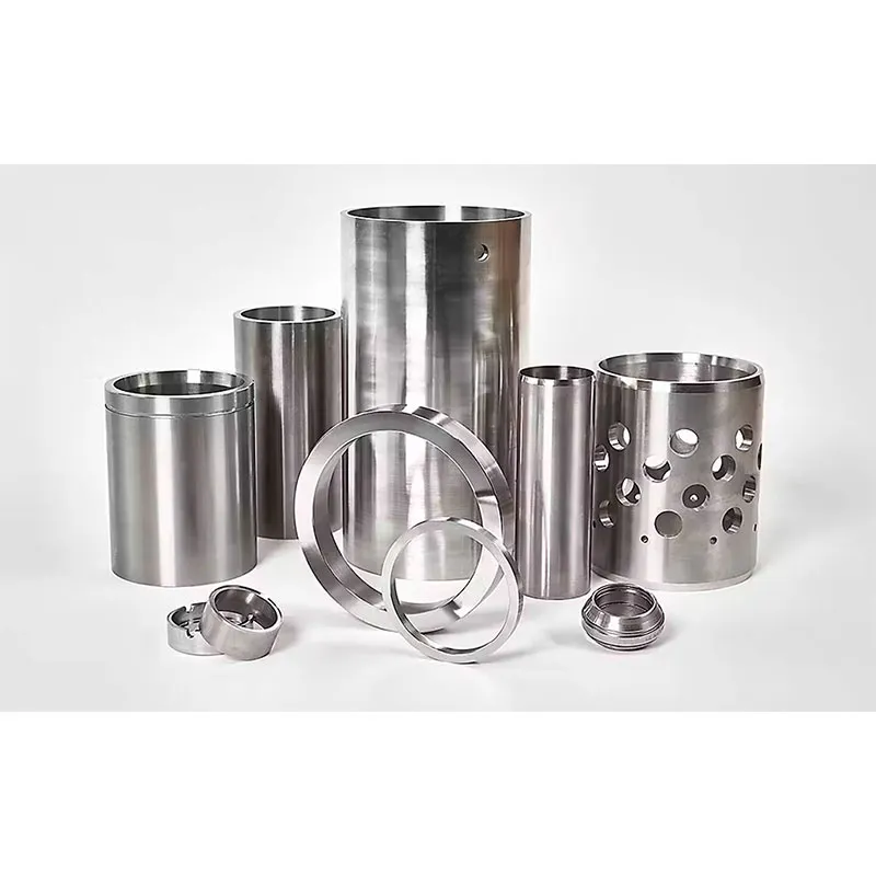
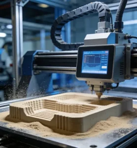
Precision prototype machining is the production of sample components through controlled machining processes, commonly CNC milling, CNC turning, drilling, boring, and related operations. These processes remove material from a workpiece to create the required geometry.
CNC prototype machining is a closely related term commonly used when computer-controlled machining is selected to produce functional sample parts. Depending on the project, a machined prototype may be used to evaluate dimensions, assembly interfaces, surface conditions, or selected functional requirements.
For example, a machined housing prototype can help engineers verify mounting-hole positions, check the fit of mating components, and assess whether tools can access important features during assembly. These checks provide useful engineering feedback before the design moves to a larger production stage.
However, a prototype is only meaningful when its manufacturing method matches the purpose of the test. A part made for a visual review does not require the same material and inspection controls as a part intended for structural or thermal testing.
How Does CNC Machining Support Prototype Development?
CNC machining allows engineers to produce and revise parts without first creating dedicated casting tooling. When the design changes, the machining program and manufacturing plan can be updated to produce another iteration.
A typical workflow includes:
- Reviewing the CAD model, technical drawing, and intended use of the prototype.
- Selecting a material and a suitable machining process.
- Planning workholding, machining operations, and inspection requirements.
- Producing the prototype and checking specified dimensions.
- Reviewing test results, recording design changes, and preparing the next revision.
The workflow should reflect the decision the prototype needs to support. An assembly-fit check may focus on hole locations and mating surfaces, while a functional test may also require a specific material grade, material condition, surface finish, or additional documentation.
2. When Should Engineers Choose Precision Prototype Machining?
Precision prototype machining is useful when a development team needs a physical part to answer specific engineering questions before committing to production.
Fit and Assembly Validation
A physical prototype can reveal problems that are difficult to identify from a CAD model alone. Examples include interference between components, misaligned mounting holes, insufficient clearance, and difficulties installing fasteners.
For assembly validation, identify the features that determine whether the part fits correctly. These may include:
- Mounting faces and hole patterns.
- Locating features and datum surfaces.
- Threads and fastener interfaces.
- Bearing seats and mating bores.
- Sealing surfaces and assembly clearances.
Not every dimension has the same functional importance. A useful drawing distinguishes the dimensions and geometric relationships that control assembly from features that can be evaluated using appropriate general tolerances.
The goal is not to make every dimension as tight as possible. It is to produce a prototype that can reliably answer the assembly questions under investigation.
Functional and Mechanical Testing
When a prototype will undergo functional testing, its material and manufacturing condition must be appropriate for the intended evaluation.
For example, a bracket used to check assembly geometry may not need the same material specification as a bracket subjected to repeated loading. A prototype intended to evaluate corrosion resistance should use a material and surface condition appropriate for that test.
Engineers should distinguish between three different objectives:
- Geometry validation: checking dimensions, clearances, mounting locations, and assembly fit.
- Functional validation: checking whether the component performs its intended task under defined conditions.
- Material or process validation: evaluating properties that depend on the specified material, manufacturing route, or post-processing.
A machined prototype may be suitable for the first objective without fully representing the material behavior of a future cast or heat-treated component. If test results will inform structural or safety-related decisions, define the required material condition, manufacturing route, and acceptance criteria before ordering.
Low-Volume Development and Design Iteration
Machining can be practical when a small number of samples is needed and the design is still changing. It allows engineers to evaluate revisions without first investing in dedicated casting tooling.
It is particularly suitable when the part can be produced economically from available stock and the required geometry is accessible to cutting tools.
However, prototype machining is not automatically the lowest-cost option for every design. Deep internal cavities, complex enclosed passages, extensive material removal, and difficult-to-machine alloys can increase machining time and material waste.
The appropriate process depends on the part geometry, material, quantity, testing objective, and likely production route.
3. How to Select Materials for Precision Prototypes
Material selection should reflect what the prototype needs to prove. A material suitable for an early fit check may not be suitable for functional testing or production qualification.
The following table provides general selection guidance. Final suitability depends on the specific alloy or grade, component design, operating environment, and required testing.
| Material group | Potential advantages | Key considerations |
| Aluminum alloys | Often suitable for lightweight components and relatively efficient machining | Evaluate strength, corrosion conditions, the specific alloy and temper, and the intended finish |
| Stainless steels | May be appropriate where corrosion resistance or grade-specific mechanical properties are required | Consider work hardening, tool wear, machining conditions, and the exact grade |
| Carbon and alloy steels | May support applications requiring specific strength, hardness, or wear characteristics | Consider heat treatment, machinability, dimensional stability, and service conditions |
| Nickel-based alloys | May be suitable for specialized thermal or corrosive environments | Evaluate the specific grade, machining difficulty, material cost, and processing requirements |
| Cobalt-based alloys | May be selected for specialized wear or high-temperature applications | Suitability depends on the alloy grade, operating conditions, and machining requirements |
Aluminum and Stainless Steel for Prototype Parts
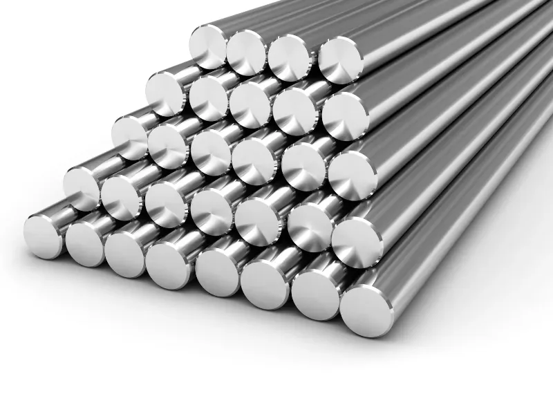
Aluminum alloys are commonly considered for housings, brackets, fixtures, and other components where weight and machining efficiency matter. The exact alloy should be selected according to the required mechanical properties, corrosion conditions, and intended use.
Stainless steel may be more appropriate when corrosion resistance or other grade-specific properties are important. Different stainless steel grades can have substantially different machinability and performance, so the general material name is not a sufficient purchasing specification.
For either material, identify the required grade and condition rather than relying only on a broad description such as “aluminum” or “stainless steel.”
Carbon Steel and Special Alloys
Carbon and alloy steels may be appropriate when strength, hardness, wear resistance, or heat-treatment requirements influence the component design.
If the final part will be heat-treated, clarify whether the prototype must be evaluated before or after the same treatment. The manufacturing condition can affect the relevance of the test results.
Nickel-based and cobalt-based alloys may be considered for specialized applications, but their selection should be driven by defined service requirements rather than the assumption that a more specialized alloy is always better.
When choosing a difficult-to-machine alloy, confirm that the proposed process can produce the required features and satisfy the inspection requirements. Material availability, stock dimensions, and the intended production route may also influence the decision.
Match the Prototype Material to the Test Objective
Before placing an order, answer three questions:
- What needs to be validated? Geometry, assembly fit, mechanical behavior, corrosion resistance, thermal performance, or another requirement?
- Must the material represent production? A substitute may be acceptable for an initial fit check but unsuitable for representative performance testing.
- Will post-processing affect the result? Heat treatment, coating, finishing, and other processing steps may influence the final condition.
If an alternative material is acceptable, define the properties that must be preserved and obtain approval for the specific substitution. A general statement such as “any aluminum” may leave too much room for interpretation when the material affects the test result.
4. Which Tolerances and Features Need the Most Attention?
Precision prototype machining requires clear dimensional requirements, but specifying extremely tight tolerances on every feature is not necessarily the best approach. Tolerances should reflect function, assembly requirements, measurement capability, and the consequences of dimensional variation.
Identify Critical Dimensions, Datums, and Geometric Requirements
Start by identifying the features that control how the part locates, aligns, seals, rotates, or connects to other components.
Depending on the design, these may include:
- Mounting-hole positions and hole-to-hole relationships.
- Bearing seats, bores, and shaft interfaces.
- Sealing surfaces and mating faces.
- Threaded holes and fastener locations.
- Reference surfaces used to establish part orientation.
- Geometric relationships such as perpendicularity, parallelism, position, or flatness.
Datums provide a reference framework for defining and inspecting certain geometric requirements. If the drawing uses geometric dimensioning and tolerancing (GD&T), the datum structure and specified controls should reflect how the component functions and is assembled.
A drawing should not rely on an informal instruction such as “machine to high precision” when a specific dimensional or geometric requirement is necessary. The relevant feature, tolerance, datum reference, and inspection expectation should be stated clearly.
Threads, Bores, Sealing Surfaces, and Mating Features
Different features create different manufacturing and inspection concerns.
| Feature | What to clarify before machining |
| Threaded holes | Thread specification, location, depth, and any requirements for thread inspection |
| Precision bores | Diameter tolerance, geometric relationships, surface requirements, and measurement method |
| Sealing surfaces | Specified geometry, surface finish, and the mating sealing design |
| Mounting-hole patterns | Hole sizes, positional relationships, datum references, and assembly clearances |
| Mating faces | Required orientation, contact area, surface condition, and relationship to adjacent features |
The appropriate controls depend on the component’s function. For example, a bore used only for clearance may not require the same inspection approach as a bore that locates a bearing or controls a moving interface.
Surface finish should also be specified where it affects sealing, friction, wear, appearance, or assembly. Identify the affected surface and the applicable finish requirement instead of relying on vague descriptions such as “smooth finish.”
Plan Inspection Around the Requirements
Inspection should be planned before production, especially when a prototype will be used to approve a design or compare manufacturing alternatives.
A practical inspection plan identifies:
- Which dimensions and geometric requirements are critical.
- Which features require recorded measurements.
- Which measuring equipment or inspection method is appropriate.
- Whether material records, surface checks, or additional tests are required.
- What documentation must accompany the delivered parts.
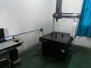
The measuring method should be appropriate for the tolerance and feature being evaluated. A measurement result is only useful when the measurement setup, reference conditions, and interpretation match the requirement.
If a particular inspection report or test is necessary for design approval, state it in the RFQ and confirm its availability before ordering. Do not assume that every supplier offers the same inspection equipment or documentation.
5. How Does Part Design Affect Prototype Machining Feasibility?
A design may be technically machinable but still difficult or expensive to produce. Tool access, workholding, feature depth, material removal, and inspection access all affect feasibility.
Thin Walls, Deep Pockets, and Tool Access
Thin walls can deflect under cutting forces, while deep pockets and narrow slots may require long or specialized tools. These conditions can increase the risk of vibration, tool deflection, burrs, and dimensional variation.
Where the design allows, consider whether walls can be made more robust, deep features can be reduced, or internal corners can accommodate practical tool geometry. Any design change must preserve the part’s functional requirements.
Internal features also need to be accessible to the cutting tool and, where necessary, to inspection equipment. A feature that is difficult to machine may also be difficult to verify.
If a design contains complex internal passages, enclosed cavities, or geometry that cannot be reached with conventional cutting tools, discuss alternative manufacturing processes before finalizing the prototype plan.
Workholding and Machining Setups
The part must be held securely while material is removed. Complex shapes may require multiple setups, custom fixtures, or carefully planned reference surfaces.
Additional setups can introduce positioning variation. Where multiple features must maintain a precise relationship, engineers and machinists should discuss how the part will be located and which datum references will be maintained between operations.
For prototype parts with irregular geometry, identify suitable clamping surfaces early. Workholding should not distort thin or flexible features, and clamping areas should not interfere with important finished surfaces.
Design for Manufacturability Before Quotation
A design-for-manufacturability (DFM) review can identify features that may affect cost, feasibility, or dimensional control before the order is placed.
The review may consider:
- Whether standard cutting tools can reach the required geometry.
- Whether thin walls or long tools create machining risks.
- Whether several features can be completed in fewer setups.
- Whether the specified tolerances are justified by function.
- Whether inspection equipment can access critical features.
- Whether another manufacturing route would be more suitable.
A DFM review should not change the design’s functional intent without approval. If a supplier recommends changing a radius, wall thickness, tolerance, or datum arrangement, review the proposal against the engineering requirements before accepting it.
6. When Should You Consider Casting Instead of Machining From Solid Stock?
CNC machining and casting solve different manufacturing problems. Machining removes material from stock, while casting forms a part in a mold and may be followed by machining to finish critical features.
The better choice depends on geometry, material, quantity, dimensional requirements, tooling considerations, and the intended production stage.
Machining From Solid Stock
Machining from solid stock is worth considering when:
- Only a limited number of prototypes are needed.
- The part can be produced from available stock dimensions.
- Critical features require direct machining and inspection.
- The design is still changing and dedicated tooling would be premature.
- The geometry is accessible to the selected machining process.
Limitations may include material waste, long machining cycles for complex shapes, and difficulty producing certain internal or near-net-shape features.
Casting Followed by CNC Machining
Casting may be worth evaluating when the part has a complex overall shape, significant material volume would otherwise be removed, or the intended production quantity justifies the tooling and process-development effort.
Depending on the geometry, material, and casting method, a casting can provide a near-net-shape starting point. CNC machining can then finish selected interfaces, such as mounting faces, holes, bores, and other features with specified dimensional requirements.
This combined approach can be useful when a component needs both a complex body shape and accurately machined functional interfaces. However, casting introduces its own design constraints, tooling requirements, material considerations, and inspection needs.
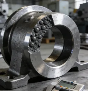
A machined prototype made from solid stock may also behave differently from a cast production component. Differences in material structure, manufacturing history, and post-processing can affect how well the prototype represents the final part. If these differences are relevant to the test, the prototype route should be selected accordingly.
Compare the Processes Before Committing
| Decision factor | Machining from solid stock | Casting followed by machining |
| Early design iterations | Can suit accessible geometries when design changes are expected | Tooling and process changes may make early revisions more involved |
| Complex overall geometry | May require extensive material removal or multiple operations | May form complex external geometry more efficiently, depending on the process |
| Critical functional features | Can machine specified interfaces directly from stock | Can finish critical interfaces after casting |
| Material use | Can generate substantial chips when much of the stock is removed | May reduce some material removal, depending on the casting design and allowances |
| Production planning | Depends on machining time, stock availability, and quantity | Requires consideration of tooling, casting, machining, and inspection |
| Prototype representativeness | May differ from the final part if production uses casting | Can better represent the intended route when the prototype uses a representative material and process |
There is no universally superior process. For a prototype that must represent a cast component, machining from solid stock may be sufficient for fit checks but inadequate for some production-process validation objectives.
Before choosing a route, clarify the expected production quantity, geometry, material specification, critical features, and validation goals with the manufacturing supplier.
7. What Information Should Be Included in a Prototype Machining RFQ?
A clear RFQ helps a supplier assess feasibility, identify risks, and prepare a quotation based on the actual requirements rather than assumptions.
For precision prototype machining, provide the following information wherever applicable.
CAD Files, Technical Drawings, and Revision Control
Supply the current 3D CAD model and a controlled technical drawing when available. The model communicates geometry, while the drawing should define the required dimensions, tolerances, datums, material specification, surface requirements, and other manufacturing notes.
Identify the part number and revision on the supplied files. If the model and drawing are inconsistent, resolve the discrepancy before production rather than allowing the supplier to choose which version to follow.
For projects with frequent design changes, confirm which file revision is approved for quotation and manufacture. A correctly machined part can still be unusable if it was produced from an obsolete design.
Material, Quantity, and Required Condition
State the required material grade and condition. If alternatives are acceptable, identify which properties must be preserved and which substitutions require approval.
Specify the number of prototypes required and, if known, the expected follow-on quantity. These details can affect process planning, setup decisions, and the suitability of different manufacturing routes.
If the component requires heat treatment, coating, finishing, or another post-processing operation, include it in the RFQ. Clarify whether the prototype must be tested before or after the relevant treatment.
Tolerances, Inspection, and Documentation
Highlight critical dimensions and geometric requirements. If particular measurements need to be recorded, state the required inspection report or documentation.
Where material traceability, material certificates, test reports, or other records are required, define those expectations before ordering. Confirm the required scope rather than assuming that unspecified documents will automatically be included.
Surface Finish, Packaging, and Delivery Requirements
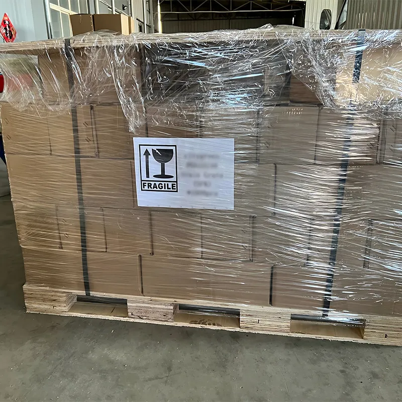
Describe any required surface finish, deburring, edge treatment, marking, or protection of finished surfaces. Packaging should protect the component against damage and contamination during handling and transport.
Include the delivery destination and target date when known. The supplier should confirm feasibility based on the material, geometry, production plan, and inspection requirements rather than relying on an assumed standard lead time.
Prototype Machining RFQ Checklist
Before sending the request, confirm that you have included:
- Current CAD model and technical drawing, with part number and revision.
- Material grade, condition, and any approved alternatives.
- Prototype quantity and expected future production needs, if known.
- Critical dimensions, tolerances, datum references, and surface requirements.
- Required post-processing, finishing, and deburring.
- Inspection scope and required quality documentation.
- Packaging requirements and delivery destination.
- Target delivery date and any special handling requirements.
- A clear statement of the prototype’s purpose and the test or decision it must support.
Not every project requires every item. The objective is to define the requirements that influence manufacturing feasibility, part acceptance, and the usefulness of the prototype test results.
8. How Can a Prototype Transition to Small-Batch Production?
A successful prototype is a step toward production, not automatic proof that the design and manufacturing process are ready for repeat orders.
Before moving to a small batch, review the prototype against the original requirements and document the findings.
Review Test Results and Design Revisions
Compare measured dimensions and functional test results with the acceptance criteria. Record assembly problems, unexpected interference, material concerns, or deviations from the drawing.
If a design revision is required, update the CAD model and drawing and clearly identify the new revision. This prevents the engineering team and supplier from working from different versions.
When a failure occurs, determine whether it originates from the design, material, manufacturing process, or test setup before making changes.
Establish Repeatable Inspection Criteria
A prototype may be accepted after an individual engineering review, but a small batch requires a clear understanding of how conformity will be assessed across multiple parts.
Identify the characteristics that need to be measured, the relevant acceptance limits, and the inspection method. If the project requires a formal inspection plan or additional documentation, establish those requirements before the next order.
The appropriate level of inspection depends on part function, risk, customer requirements, and the intended production stage.
Confirm the Production Route
Before scaling up, reassess whether machining from solid stock remains suitable or whether another process, such as casting followed by CNC machining, better fits the expected geometry and quantity.
A change in manufacturing route may affect material properties, dimensional behavior, surface condition, tooling, and inspection requirements. It should therefore be evaluated as a manufacturing change rather than treated as a simple cost adjustment.
The next production stage should proceed only after the team has agreed on the design revision, material specification, critical features, acceptance criteria, and manufacturing assumptions.
Frequently Asked Questions About Precision Prototype Machining
What is precision prototype machining used for?
Precision prototype machining is used to produce metal sample parts for checking dimensions, assembly fit, functional features, and manufacturing feasibility before production. Its suitability for mechanical or material-performance testing depends on the selected material and how representative the prototype is of the intended production part.
What tolerances can precision prototype machining achieve?
Achievable tolerances depend on the material, part geometry, feature size, machining process, workholding, equipment, and inspection method. There is no single tolerance that applies to every machined prototype. Specify the required limits on the drawing and ask the supplier to review critical features before quoting.
Is CNC machining better than casting for prototypes?
Neither process is universally better. CNC machining from solid stock can suit early prototypes and accessible geometries when design changes are expected. Casting followed by CNC machining may be more appropriate for certain complex shapes or when the intended production route uses cast components. The choice should reflect the validation objective, material, geometry, quantity, and production plan.
What files are needed for a prototype machining quote?
A current 3D CAD model and technical drawing are useful starting points. The request should also identify the part revision, material, quantity, critical tolerances, surface requirements, post-processing, inspection expectations, and delivery requirements. Additional documentation may be necessary for projects with specific quality or traceability requirements.
Should the prototype material match the production material?
It should match when material properties affect the test result. A substitute may be acceptable for an initial form or fit check, but the buyer should define the required property match and approve the specific alternative before testing.
Can a machined prototype be used to validate a cast production part?
It can be useful for checking selected geometry and assembly interfaces, but it may not reproduce every characteristic of the final cast component. If the validation depends on material structure, casting-related behavior, or production-specific processing, a prototype made through a representative manufacturing route may be necessary.
Conclusion
Precision prototype machining helps engineering teams turn a design into a measurable physical part before committing to production. The most useful results come from selecting a material that matches the test objective, defining functional tolerances clearly, reviewing machining accessibility, and planning inspection before the order is placed.
For B2B projects, a complete RFQ should also define drawing revisions, material condition, documentation, finishing, packaging, and delivery requirements. These details help the supplier evaluate the actual manufacturing scope and reduce ambiguity around part acceptance.
When a component has complex geometry or is intended for cast production, comparing machining from solid stock with casting followed by CNC machining can help identify a more suitable development path. The right choice depends on what the prototype must prove and how the validated design is expected to be manufactured in the next production stage.