Abstract: A practical step-by-step guide to select the right thermocouple protection tube for long-lasting, accurate high-temperature industrial measurement.
Selecting the right thermocouple protection tube prevents premature failure, ensures accurate temperature readings, and extends service life in harsh high-temperature industrial environments.
For metallurgy, cement production, thermal power, and petrochemical facilities, a poorly chosen protection tube is one of the most common hidden causes of unplanned downtime and unreliable process data.
This guide walks through a practical, step-by-step selection framework that balances temperature resistance, corrosion performance, mechanical durability, and measurement response to match real-world operating conditions.
Why the Right Thermocouple Protection Tube Matters for High-Temperature Measurement
A thermocouple itself is only responsible for generating a temperature signal.
The protection tube acts as the primary physical barrier that separates the sensitive thermocouple junction from furnace atmospheres, flue gases, molten materials, abrasive dust, and mechanical impact.
Even a high-accuracy class 1 thermocouple will produce unstable readings or fail completely if the protection tube cracks, corrodes through, or softens at operating temperature.
In continuous industrial operations, unexpected protection tube failure often forces teams to shut down thermowell access, drain process fluid, or even pause a production run to replace the assembly.
Many facilities waste hours of maintenance time and thousands of dollars in lost output not because they selected a low-cost tube, but because they based the decision only on the maximum advertised temperature rating without accounting for other operating conditions.
Step 1: Match Material to Continuous Operating Temperature
Temperature rating is the first and most fundamental factor in selection, but it is also one of the most frequently misinterpreted.
Manufacturers often list a peak short-term temperature rating that the material can survive for a few hours, not the continuous operating temperature where it can maintain structural integrity for thousands of hours of service.
Common Material Temperature Limits and Practical Constraints
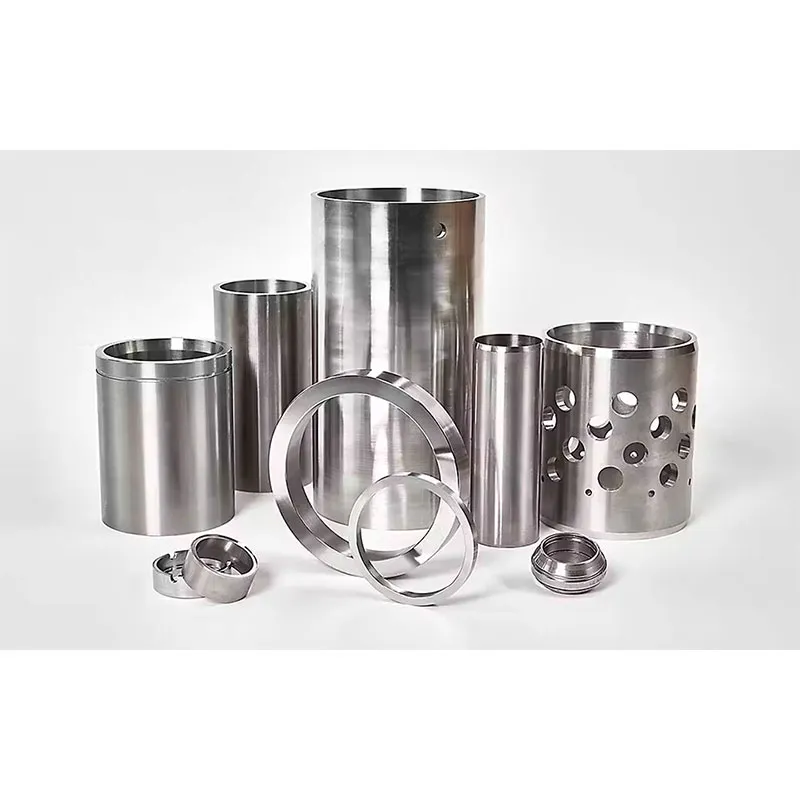
Different categories of high-temperature resistant parts serve distinct temperature bands, and no single material performs well across every possible range:
- 316 stainless steel: Suitable for continuous use up to roughly 600°C. It offers good general corrosion resistance but will rapidly oxidize and lose strength above this threshold.
- Incoloy 800: Reliable for long-term operation at temperatures up to 1100°C in oxidizing and neutral atmospheres. It performs well in steam and carburizing environments, making it a common choice for boiler flue gas measurement.
- Inconel 600: Designed for continuous service up to around 1150°C, with excellent resistance to both oxidation and reduction. It is widely used in heat treatment furnace applications where rapid temperature cycling occurs.
- High-purity alumina ceramic: Capable of continuous operation above 1600°C, and remains stable even in many molten metal contact scenarios. It is far more brittle than metal alloys, however, and can fracture under thermal shock or mechanical impact.
When matching material to temperature, always use the continuous service rating as your baseline rather than the peak laboratory rating.
If your process regularly cycles between room temperature and maximum operating temperature, you should also reduce the effective temperature limit further to account for repeated thermal expansion and contraction.
Step 2: Evaluate Corrosion and Chemical Exposure Risks
Even if a material can withstand the nominal process temperature, unexpected chemical exposure can destroy a thermocouple protection tube in a fraction of its expected service life.
In many high-temperature processes, the surrounding atmosphere contains corrosive components that are not immediately obvious from basic process flow diagrams.
Alloy Selection for Chloride, Sulfide and Molten Salt Environments
Different corrosion-resistant parts behave very differently when exposed to specific aggressive media, and there is no universal alloy that works for every corrosive high-temperature scenario:
- In environments with high sulfur content, common in heavy fuel oil-fired furnaces, ordinary 300-series stainless steels will suffer rapid sulfidation attack. Incoloy 825 offers far better resistance to both sulfur compounds and reducing acid conditions at temperatures up to 850°C, though this limit should be reduced below 700°C under strongly reducing conditions.
- For processes containing high chloride concentrations, such as waste incineration or certain molten salt systems, standard stainless steels will develop stress corrosion cracking. Inconel 625 provides strong resistance to chloride ion attack alongside excellent high-temperature mechanical strength, with a typical continuous service temperature range of 980°C to 1100°C, which shifts depending on exact alloy composition and surrounding atmosphere.
- In strongly carburizing or nitriding atmospheres, even high-nickel alloys can degrade over time. In these cases, a dense alumina or silicon carbide protection tube often delivers far longer service life than any metallic alloy.
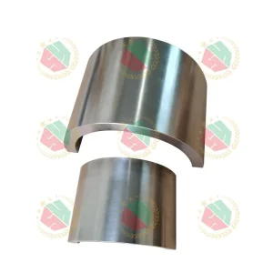
The most common mistake here is selecting a high-temperature alloy without reviewing the full process gas composition.
Even a small percentage of corrosive trace components that seem negligible on paper can lead to unexpected tube thinning and failure after several hundred hours of operation.
Step 3: Account for Mechanical Stress, Abrasion and Flow Velocity
Temperature and corrosion performance alone do not guarantee long service life.
Many industrial installations expose the thermocouple protection tube to continuous mechanical forces that can wear or break the assembly long before corrosion becomes the limiting factor.
High-velocity flue gas carrying fly ash, cement clinker dust, or mineral particles will steadily abrade the outer surface of metallic protection tubes, even when the material itself is chemically compatible with the process.
In these situations, a thicker walled alloy or a wear-resistant ceramic outer sleeve can drastically extend service life.
Protection tubes that are installed horizontally or extend a long distance into a process duct are also subject to vibration and bending stress.
Under these conditions, a thin-walled high-nickel alloy tube may bend or fracture, even at temperatures well below its maximum rated limit.
For these mechanically demanding applications, selecting a slightly lower temperature-rated but higher structural strength material often results in a more reliable overall installation.
Step 4: Balance Thermal Response Time and Structural Strength
A thicker, mechanically robust protection tube will slow down the speed at which the internal thermocouple can detect changes in process temperature.
This creates a fundamental tradeoff that many engineers overlook during selection.
If your control system relies on fast, dynamic temperature feedback to adjust combustion, feed rate, or safety interlocks, a heavy thick-walled protection tube can introduce enough measurement lag to degrade process control performance.
A general rule of thumb is that doubling the wall thickness of a metal protection tube roughly doubles the thermal time constant of the assembly.
For applications where fast response is critical, you can select a carefully sized thin-wall alloy tube with sufficient mechanical strength, or use a mineral-insulated compact thermocouple assembly with a smaller outer diameter.
The goal is not to maximize strength at the cost of measurement performance, nor to minimize wall thickness so much that the tube breaks after a few weeks of operation.
For three of the most common installation scenarios, you can use these quick reference guidelines:
- For long horizontal insertion into large process ducts, select a minimum 2.5mm wall thickness to resist bending under vibration
- For high-velocity dust-laden flue gas, select 3mm or greater wall thickness to extend abrasion life
- For frequent cold-to-hot thermal cycling, avoid maximum thin-wall designs that can accelerate fatigue cracking
Common Selection Mistakes to Avoid in Industrial Applications
Even experienced teams regularly repeat the same avoidable errors when specifying thermocouple protection tubes:
- Selecting material based only on peak process temperature, ignoring the continuous operating duty cycle → Quick check: confirm 30-day average operating temperature
- Assuming a high-temperature alloy will automatically resist all forms of chemical corrosion → Quick check: review full process gas composition
- Overlooking thermal shock risk when switching between cold startup and full operating temperature → Quick check: count typical temperature cycles per week
- Choosing the smallest possible outer diameter to improve response time, without accounting for abrasion and vibration in the duct → Quick check: verify flow velocity and dust loading
Taking an extra 15 minutes to cross-reference all operating conditions against material properties before finalizing a specification can prevent weeks of unplanned maintenance and lost production later.
Recommended Material Comparison Table
| Material Grade | Maximum Continuous Temperature | Primary Corrosion Strength | Typical Industrial Application | Key Limitation |
| 316 Stainless Steel | 600°C | General atmospheric corrosion | Low-temperature flue gas, standard industrial ovens | Poor performance above 600°C |
| Incoloy 800 | 1100°C | Steam, mild carburization | Boiler outlets, heat treatment furnaces | Limited resistance to strong chlorides |
| Inconel 600 | 1150°C | Oxidation, thermal cycling | Batch heat treatment, high-temperature ovens | Vulnerable to severe sulfidation |
| Inconel 625 | 980°C–1100°C | Chloride, reducing acids | Waste incineration, molten salt processes | Higher material cost |
| Incoloy 825 | 850°C (700°C max under strong reduction) | Sulfide, dilute acid | Heavy oil-fired furnace flue gas | Not for long-term use above 900°C |
| High-purity Alumina | 1600°C | Molten metal, strong corrosives | Molten steel, high-temperature kilns | Brittle, sensitive to thermal shock |
Frequently Asked Questions
Can I use the same protection tube material for both high temperature and heavy corrosion?
There is no single material that performs optimally for every combination of extreme temperature and extreme corrosion.
For the most demanding mixed conditions, many facilities use a layered design that combines a high-temperature alloy inner liner with a corrosion-resistant or abrasion-resistant outer layer, rather than trying to force one single material to cover all requirements.
How does wall thickness affect the service life and temperature response of a thermocouple protection tube?
Increasing wall thickness improves mechanical strength and extends service life in abrasive environments, but it also increases the thermal mass of the tube.
This slows down temperature response, meaning the thermocouple will take longer to reflect rapid changes in the process temperature.
For most general industrial applications, a wall thickness between 1.5mm and 3mm provides a reasonable balance between durability and measurement performance.
What is the typical service life of an industrial thermocouple protection tube under normal working conditions?
Under stable, non-abrasive, non-corrosive conditions, a properly selected alloy protection tube can deliver 1 to 3 years of continuous service.
In highly abrasive or heavily corrosive high-temperature processes, expected service life may drop to 3 to 6 months.
The most reliable way to estimate real service life is to reference historical performance data from similar installations in your specific industry, rather than relying only on generic manufacturer datasheets.