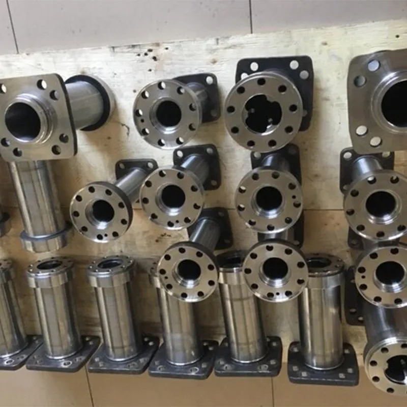
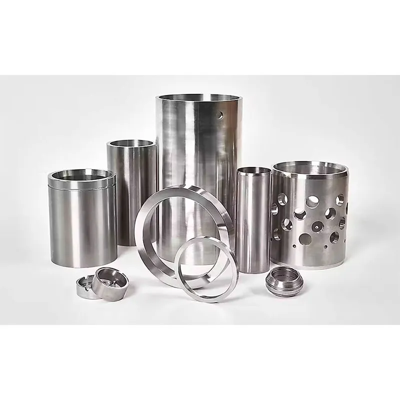
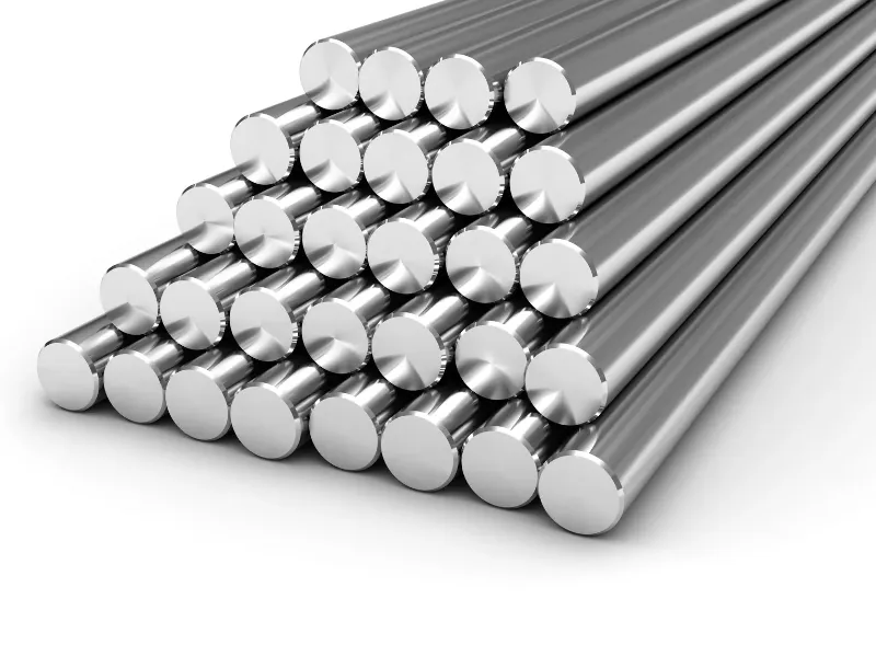
Lost foam casting (evaporative pattern casting) is a near-net-shape metal forming technology that uses expendable EPS foam patterns instead of solid wax or wood patterns. Molten metal vaporizes the foam pattern and fills the mold cavity, producing finished castings with no parting lines and no need for sand cores. Improper process control leads to carbon inclusions, gas porosity and dimensional variation, which increases rejection rates for lost foam casting parts. This guide walks through the full process flow, technical specifications, pros and cons, common casting defects, and provides a direct comparison with investment casting, helping mechanical and procurement engineers select the right manufacturing method for custom metal components.
1. What Is Lost Foam Casting?
Lost foam casting is a lost-pattern casting method that eliminates traditional sand casting limitations. Instead of splitting the mold with parting lines and assembling sand cores, manufacturers produce a full-size expanded polystyrene (EPS) foam replica of the final part. The foam pattern is coated with a thin refractory layer, buried in loose, unbonded dry sand, and compacted under vacuum pressure. When molten metal is poured into the gating system, the high temperature pyrolyzes the foam pattern into gas and carbon residue. The gas escapes through the coating and dry sand, and the liquid metal fully replaces the foam shape to form a solid metal casting after cooling.
The biggest difference from conventional casting: no parting lines, no draft angles, and no separate sand cores. This unique feature makes the process ideal for complex parts with curved internal flow passages.
2. Step-by-Step Lost Foam Casting Process Flow
The full production sequence follows 7 clear stages without complex mold assembly:
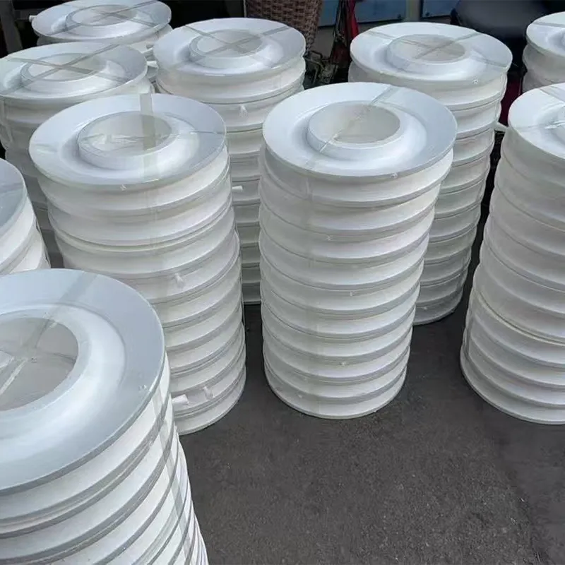
- EPS Foam Pattern Fabrication: Cut or injection-mold solid EPS foam into the exact shape of the finished casting; glue separate foam segments together to form complex assemblies.
- Pattern Tree Assembly: Group multiple foam patterns onto a foam sprue and runner system to form a casting cluster, improving production efficiency.
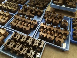
- Refractory Coating & Drying: Dip the entire foam cluster into water-based refractory slurry repeatedly to build up a dense, gas-permeable coating; fully air-dry each layer to prevent coating cracking during pouring.
- Sand Filling & Vacuum Compaction: Place the coated foam cluster inside a casting flask; fill the flask with loose dry silica sand and vibrate the flask to fully pack sand around every surface. Apply continuous vacuum to hold the sand rigid without chemical binders.
- Molten Metal Pouring: Pour liquid alloy into the sprue; the hot metal vaporizes the EPS pattern and progressively fills the mold cavity. Vacuum pressure keeps the sand stable while gas from foam decomposition vents out of the sand bed.
- Cooling & Shakeout: Let the casting solidify completely. Release the vacuum and shake out the loose dry sand, which can be recycled for subsequent batches.
- Finishing Operations: Cut off the gating system, remove residual coating, blast clean the surface, and perform machining to meet final dimensional requirements.
3. Key Technical Specifications: Tolerance & Surface Quality
Lost foam casting delivers consistent dimensional accuracy and surface finish between conventional sand casting and investment casting. All values below reflect typical industrial production standards.
- Dimensional Tolerance: ISO 8062 CT7–CT9; linear tolerance reaches ±0.5–1.0 mm for most dimensions. Extra tolerance loss (±0.5 mm) occurs at every glue joint between foam pattern segments.
- Surface Roughness (Ra): 6.3–12.5 μm; a faint foam bead texture remains on the casting surface, smoother than green sand casting but less polished than investment castings.
- Minimum Wall Thickness: 3 mm for aluminum alloys; 4.5 mm for ferrous metals (cast iron and steel). Thinner walls risk premature metal solidification and cold shut defects.
- Machining Allowance: 1.5–3 mm per surface; the near-net-shape design drastically reduces the amount of post-casting machining work.
- Draft Requirement: Zero draft angle required. Vertical walls and undercut features can be cast directly without pattern removal restrictions.
4. Main Advantages of Lost Foam Casting
Lost foam casting delivers clear economic and design benefits for medium-to-large complex castings:
- No Parting Lines or Flash: The single-piece foam pattern removes mold split lines entirely. There is no flash to grind off, cutting finishing labor significantly.
- No Sand Cores Required: Complex internal cavities, curved flow channels and blind passages can be integrated directly into the foam pattern. Core shift and core breakage defects are completely eliminated.
- Zero Draft Angle Design Freedom: Designers do not need to add draft angles for pattern ejection, which simplifies part geometry and optimizes structural strength.
- Low Tooling Cost & Short Lead Time: EPS foam patterns are cheap to produce with CNC hot-wire cutting; prototype lead time can be shortened to 1–3 days without expensive metal injection dies.
- Recyclable Dry Sand: Unbonded dry sand can be reused repeatedly after shakeout, cutting raw material costs and reducing industrial waste compared to resin-bonded sand casting.
- High Batch Consistency: The fully sealed mold and vacuum compaction minimize dimensional variation across production runs, suitable for batch sizes from small prototypes up to mass production.
5. Limitations & Typical Defects in Lost Foam Casting
5.1 Core Limitations of the Process
Lost foam casting has inherent technical boundaries that cannot be fully eliminated by process tuning:
- Precision cannot match investment casting. It cannot achieve CT4–CT6 tight tolerance grades or ultra-smooth mirror surfaces.
- Carbon contamination is an unavoidable risk for steel and iron castings, caused by EPS foam pyrolysis.
- Thin-wall components (below the minimum wall thickness threshold) frequently suffer from misruns and incomplete filling.
- The foam bead texture leaves a visible surface grain that cannot be fully eliminated without heavy grinding.
- The process is not suitable for high-temperature superalloys and titanium alloys due to severe carbon pickup and gas generation.
5.2 Most Common Defects: Carbon Inclusions & Porosity
Most lost foam casting failures stem from two root defects: carbon inclusions and gas porosity.
Carbon Inclusions (Lustrous Carbon Defect)
When EPS foam decomposes under molten metal heat, incomplete gasification leaves solid carbon soot and tar residues trapped against the casting surface. The carbon dissolves into ferrous metal, causing surface carburization, poor machinability and inconsistent heat treatment performance.
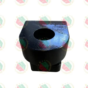
Main triggers: excessively high EPS foam density (above 24 kg/m³), low pouring temperature, and low-permeability refractory coating that blocks gas venting.
Gas Porosity
Large volumes of hydrocarbon gas are generated during foam pyrolysis. If gas cannot escape through the coating and sand fast enough, gas bubbles become trapped inside the solidifying metal, forming subsurface pinholes and blowholes. Porosity risk rises sharply when vacuum pressure is insufficient or coating permeability is too low.
Additional frequent defects include sand adhesion (burn-on), cold shuts from slow metal filling, and pattern collapse during sand compaction.
6. Lost Foam Casting vs Investment Casting (Lost Wax)
The table below compares core technical and economic metrics to support process selection:
| Metric |
Lost Foam Casting |
Investment Casting (Lost Wax) |
| Dimensional Tolerance |
CT7–CT9 (±0.5–1.0 mm) |
CT4–CT6 (±0.1–0.3 mm) |
| Surface Roughness (Ra) |
6.3–12.5 μm |
1.6–6.3 μm |
| Minimum Wall Thickness |
3 mm (Al); 4.5 mm (Iron/Steel) |
1.0–1.5 mm |
| Parting Line |
None |
Yes (from wax tree assembly) |
| Draft Angle |
0° required |
1–3° usually required |
| Main Defect Type |
Carbon inclusions, gas porosity |
Shell cracking, wax residue inclusions |
| Tooling Cost |
Low (foam patterns) |
High (metal wax injection dies) |
| Best Batch Size |
Medium to large volume (50–50,000 pieces/year) |
Small to medium precision batches |
| Suitable Part Weight |
0.5 kg to several hundred kilograms |
Typically small to medium precision parts |
Core selection rule: Choose lost foam casting for large, complex, medium-precision ferrous castings with complex internal passages. Choose investment casting for thin-wall, high-tolerance small parts requiring excellent surface finish.
7. Suitable Alloys & Typical Lost Foam Casting Parts
7.1 Applicable Metal Alloys
- Highly suitable: Grey iron, ductile iron, carbon steel, low-alloy steel, aluminum alloys (low carbon risk).
- Limited use: Stainless steel (strict foam density control required to avoid carbon pickup).
- Not recommended: High-temperature superalloys, titanium alloys, and high-precision non-ferrous alloys prone to carbon contamination.
7.2 Typical Lost Foam Casting Parts (lost foam casting parts)
This process is widely used for fluid power, automotive and industrial machinery components with complex internal cavities:
- Pump bodies, valve bodies and hydraulic manifolds with curved internal flow channels;
- Engine blocks, cylinder heads and exhaust manifolds for automotive equipment;
- Heavy-duty hydraulic housings, gearbox casings and pipe fittings;
- Compressor housings and large mechanical structural castings without thin ribs.
Structural guidance: Select lost foam casting for thick, uniform wall structures. Avoid parts with many thin ribs and ultra-thin sections, which lead to filling defects.
8. Frequently Asked Questions
8.1 Can lost foam casting produce castings with zero parting lines?
Yes. The single-piece foam pattern eliminates mold splitting entirely, so no parting line or flash appears on the finished casting. Only glue joints between foam segments leave minor dimensional offsets.
8.2 Why do steel lost foam castings suffer from carbon contamination?
The EPS foam pattern is made of polystyrene (carbon-hydrogen polymer). Pyrolysis produces large amounts of free carbon. If the foam cannot fully gasify, residual carbon penetrates the molten steel surface and raises surface carbon content. The risk is much lower for aluminum castings due to lower pouring temperature and less carbon dissolution.
8.3 Which process costs less for medium-volume large castings: lost foam or investment casting?
Lost foam casting has far lower upfront tooling cost and lower per-unit production cost for medium-to-large castings. Investment casting only becomes economical for small high-precision parts with low annual output.
8.4 What is the ideal EPS foam density to reduce carbon defects?
The optimal density range is 22–24 kg/m³ for iron and steel castings. Densities above 26 kg/m³ drastically increase carbon inclusion risk, while excessively low density (typically below 18 kg/m³) raises the risk of foam pattern collapse during sand filling.
9. Conclusion & Selection Guide
The core principle for choosing lost foam casting depends on matching the process strengths to your part geometry, tolerance requirements and production volume:
- Select lost foam casting for medium-to-large castings with complex internal flow passages, zero parting line requirements, and moderate dimensional tolerance (CT7–CT9). It cuts machining costs and shortens prototype lead time significantly.
- Avoid this process for ultra-thin wall parts, high-precision small components, and high-alloy castings sensitive to carbon pickup; pick investment casting instead.
- Control three key process parameters to minimize defects: keep EPS foam density within 22–24 kg/m³, use high-permeability refractory coating, and maintain the correct pouring temperature to ensure complete foam gasification.
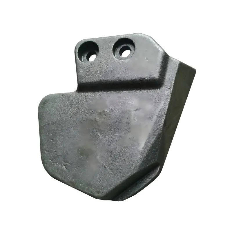
- For custom lost foam casting parts, confirm minimum wall thickness, glue joint tolerance, and alloy carbon sensitivity with your foundry before finalizing part drawings.