Turbine blades operate under extreme high-temperature gas flow, cyclic thermal stress, and corrosive media, making them one of the most challenging components for precision casting in the energy industry. Most procurement and engineering teams face consistent production challenges when sourcing turbine blades: thin-walled airfoils suffer casting shrinkage and deformation, complex internal cooling channels lead to core breakage, and superalloy material creates severe machining hardening and tight tolerance control challenges.
This guide covers alloy material selection, investment casting process control, cooling channel structure limits, dimensional tolerance standards, precision machining routes, and full NDT inspection rules for turbine blades. It targets custom drawing-based blade manufacturing, helping you reduce casting scrap, control machining allowance, and avoid costly rework on high-temperature resistant and corrosion-resistant parts.
1. Working Conditions & Core Manufacturing Challenges of Turbine Blades
Turbine blades run under continuous high heat, thermal cycling, and sulfide corrosion. First-stage gas turbine blades can sustain long-term service above 900°C. Repeated thermal expansion and contraction creates creep deformation and thermal fatigue cracks.
Geometric complexity sharply raises manufacturing difficulty:
- Thin airfoil wall thickness (often below 1 mm) causes poor molten alloy filling and uneven solidification.
- Intricate internal cooling passages require embedded ceramic cores, which easily shift or fracture during pouring.
- Complex free-form curved surfaces cannot be produced by ordinary sand casting. Only vacuum precision casting can deliver near-net-shape casting blanks.
- Nickel-based superalloys exhibit strong cold work hardening. This accelerates tool wear and destabilizes dimensional accuracy during CNC machining.
The main manufacturing pain points include casting porosity, core offset, blade profile distortion, machining deformation, and unqualified cooling film holes dimensional accuracy.
2. High-Temperature Alloy Material Selection for Cast Turbine Blades
Choosing the right superalloy is the foundation of long blade service life. Material grade must match operating temperature, corrosive environment, and creep resistance requirements. This section focuses on mainstream nickel-based superalloys widely used for cast turbine blades.
2.1 Main Superalloy Grades for Turbine Blades
- Inconel 718 (UNS N07718)
Continuous service temperature up to 700°C, with excellent tensile strength and moderate creep performance. It is widely used for low and medium-temperature turbine blades and compressor blades, offering good resistance to sour gas and wet corrosion.
- Inconel 625 (UNS N06625)
Strong resistance to pitting and crevice corrosion, compliant with NACE MR0175 sour service standards. It works steadily up to 650°C and suits blades exposed to corrosive flue gas conditions.
- Rene 80
A common equiaxed cast superalloy with balanced high-temperature strength and oxidation resistance, designed for mid-stage turbine blades operating below 950°C.
- CMSX-4 (Single-Crystal Alloy)
Top-tier creep-resistant grade for HPHT first-stage blades. Continuous service can reach 1150°C without obvious creep relaxation. Directional solidification eliminates grain boundaries to improve high-temperature stability.
2.2 Material Selection Rules Based on Service Environment
- Wet sour gas and seawater corrosion conditions: Select Inconel 625 for outstanding corrosion resistance (corrosion-resistant parts).
- Medium-temperature power generation turbine blades (≤700°C): Inconel 718 is the cost-effective option with balanced machinability and mechanical performance.
- High-temperature gas turbine hot-section blades (950–1150°C): Adopt Rene 80 equiaxed casting or CMSX-4 single-crystal directional solidification casting for anti-creep performance.
- Avoid grade over-specification: Single-crystal alloys bring much higher casting costs; only use them for the highest-temperature blade positions.
Pending verification: Exact ASTM material standards, NACE corrosion grade and long-term creep rupture data for each alloy grade.
3. Precision Investment Casting Controls for Turbine Blades
Precision casting (investment casting / lost-wax casting) is the only mature technology for producing hollow turbine blades with internal cooling channels. Poor process control will lead to shrinkage porosity, core displacement, and blade profile distortion.
3.1 Key Difficulties in Blade Investment Casting
- Thin-wall filling: Molten superalloy solidifies rapidly. Thin airfoil sections tend to form cold shut and incomplete filling.
- Ceramic core stability: Embedded cores break or shift under high-temperature metal impact, resulting in blocked or offset cooling passages.
- Solidification shrinkage: Uneven cooling causes large dimensional deviation and internal shrinkage porosity.
- Grain structure control: Equiaxed grains form easily without directional solidification, reducing high-temperature creep life.
3.2 Process Controls for Near-Net-Shape Casting
- Vacuum melting & pouring: Melt nickel superalloys under high vacuum to reduce oxygen content and avoid oxide inclusion defects. Preheat the ceramic shell mold to 900–1100°C to improve molten metal fluidity.
- Directional solidification control: Set a controlled cooling gradient (10–50°C/min cooling rate) to form columnar grains or single-crystal structures, which greatly improves high-temperature creep resistance.
- HIP hot isostatic pressing: Treat casting blanks with HIP to close internal micro-pores and shrinkage cavities, improving internal density and fatigue performance.
- Wax pattern shrinkage compensation: Pre-set mold shrinkage rate (around 1.6%–1.7% for length direction) to offset casting contraction and control overall dimensional deviation.
3.3 Casting Tolerance Baseline for Turbine Blades
Casting blank tolerance follows ISO 8062 and VDG P690 standards. For investment-cast turbine blade casting blanks:
- Airfoil profile dimensional deviation: ±0.30 mm after shrinkage compensation.
- Recommended unilateral machining allowance: 0.3–1.5 mm; thicker allowance reserved on deformed blade tip and edge areas.
- Wall thickness tolerance of cast hollow blades: ±0.15 mm for thin-walled sections.
Pending verification: Full VDG P690 tolerance grades and exact machining allowance values for different blade sizes.
4. Casting Requirements for Blade Internal Cooling Structures
Hollow turbine blades rely on internal cooling channels to reduce blade temperature. The quality of cooling passages directly determines turbine thermal efficiency, and core manufacturing decides whether the internal structure can be formed completely.
4.1 Common Cooling Channel Designs & Manufacturing Limits
Typical cooling structures include serpentine multi-pass channels, leading-edge impingement cooling cavities, trailing-edge narrow slits, and pin-fin turbulence structures.
Core casting limitations:
- Minimum practical castable wall thickness with qualified ceramic cores and vacuum pouring: 0.5 mm. This value depends on blade size and alloy type.
- Minimum core feature size: 0.5 mm diameter for small cooling film hole cores; overly thin cores will fracture during pouring.
- Narrow slit passages require high core strength and low thermal expansion to prevent deformation under high temperature.
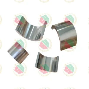
4.2 Core Fabrication & Anti-Breakage Measures
Alumina-based ceramic cores are the mainstream choice for turbine blade investment casting. Core performance requirements:
- High refractoriness: Resist temperatures above 1500°C without softening during alloy pouring.
- Low thermal expansion coefficient (below 4×10⁻⁶/K) to avoid thermal stress cracking and dimensional drift.
- Moderate flexural strength (>15 MPa) and good leachability for post-casting chemical removal.
Key anti-fracture solutions:
- Add supporting ribs on long and thin core sections to resist metal flow impact.
- Match the thermal expansion coefficient between ceramic core and superalloy to avoid thermal expansion mismatch cracking.
- Control core sintering shrinkage below 5% to keep internal channel dimensional stability.
5. Precision Machining Tolerance & Processing Scheme
Even near-net-shape investment casting blanks require 5-axis CNC precision machining to meet aerodynamic profile and assembly tolerance requirements. Superalloy machining suffers severe work hardening, which must be controlled with optimized cutting parameters.
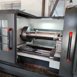
5.1 Dimensional Tolerance Requirements for Key Features
- Airfoil curved surface: GD&T profile tolerance ±0.02~0.05 mm; surface roughness Ra 0.8–1.6 μm to reduce airflow friction loss.
- Fir-tree blade root: Tensile assembly surface tolerance ±0.015 mm; surface finish Ra 0.2–0.8 μm to avoid contact fatigue under cyclic load.
- Platform sealing surface: Flatness tolerance within 0.02 mm; strict flatness control prevents gas leakage between blade rows.
- Cooling film holes: Position tolerance ±0.03 mm; hole diameter tolerance ±0.02 mm, mostly processed by EDM electrical discharge machining.
5.2 Machining Route & Tooling Selection
Standard processing workflow for cast turbine blades:
- Post-casting treatment: Shell removal, core leaching, shot blasting, and HIP densification.
- Rough machining: Remove most casting allowance with coated carbide cutters, reserve 0.2–0.4 mm semi-finishing margin.
- Semi-finishing: 5-axis linkage milling of airfoil curved surfaces, control machining deformation caused by cutting heat.
- Finishing: High-speed milling or surface grinding to achieve final profile tolerance and surface roughness.
- Secondary machining: EDM drill tiny cooling film holes on blade leading and trailing edges.
Machining tips for superalloys:
- Use low cutting speed to reduce work hardening; keep feed rate reasonably high to cut through the hardened surface layer.
- Avoid repeated shallow finishing passes that only polish the hardened skin and accelerate tool wear.
5.3 Allowance Control to Reduce Scrap Rate
Casting deformation is unavoidable, so uneven machining allowance must be considered when setting blank size:
- Increase machining allowance by 0.3–0.5 mm on blade tip, trailing edge and thin-walled areas with large shrinkage deformation.
- Use 3D blue-light scanning to measure actual casting deformation before machining, then adjust the CNC program to compensate for local dimensional deviation.
6. NDT & Quality Inspection Standards for Cast Turbine Blades
A full inspection system covers material verification, dimensional measurement, non-destructive testing, and surface quality checking, which is mandatory for high-temperature resistant parts used in gas turbines.
6.1 Non-Destructive Testing (NDT) Items
- Radiographic Testing (RT / X-ray inspection): 100% inspection to detect internal shrinkage porosity, inclusions and cold shut defects inside the blade airfoil and root.
- Ultrasonic Testing (UT): Check thick blade root sections for deep internal flaws that X-ray cannot identify.
- Penetrant Testing (PT): Inspect all blade surfaces for micro-cracks, especially on airfoil edges and blade root fillets.
- Industrial CT scanning: Verify the integrity of internal cooling passages, detect core residue and blocked cooling film holes that cannot be seen by other NDT methods.
Pending verification: NADCAP aerospace NDT standards and defect acceptance grades for turbine blade castings.
6.2 Dimensional & Surface Inspection
- CMM (Coordinate Measuring Machine): Full 3D measurement of airfoil profile, blade root size and cooling film hole position with measurement accuracy up to ±0.002 mm.
- Optical laser scanning: Compare the actual blade shape with the CAD model to quantify overall profile deviation.
- Surface roughness test: Verify Ra values on airfoil, root and sealing surfaces.
- Metallurgical inspection: Check grain structure to confirm equiaxed / directional solidified / single-crystal grain quality.
7. Frequently Asked Questions
Q1: Can ordinary equiaxed alloy replace single-crystal blades for HPHT service?
A: No. Equiaxed superalloys have grain boundaries that become weak points under high temperature and long-term load. Single-crystal CMSX-4 eliminates grain boundaries and maintains creep stability above 1000°C, which is irreplaceable for first-stage hot-section blades.
Q2: What is the minimum wall thickness that can be cast for cooling channel turbine blades?
A: With high-purity alumina ceramic cores and vacuum pouring, the practical minimum castable wall thickness is 0.5 mm. This limit varies with blade geometry and alloy selection. Thinner walls will lead to incomplete filling and high scrap rates.
Q3: How much machining allowance should be reserved for investment casting blanks?
A: The baseline unilateral allowance is 0.3–1.5 mm. Increase the allowance by 0.3–0.5 mm on areas with large casting deformation such as blade tips and trailing edges to avoid local material shortage during machining.
Q4: Which inspection method can detect internal blockage of cooling passages?
A: Industrial CT scanning is the most reliable method to inspect internal cooling channel blockage, core residue and uneven wall thickness without damaging the casting. X-ray can only detect large blockages, while small core residues can only be identified by CT scanning.
8. Conclusion & Next Steps
Manufacturing qualified turbine blades requires coordinated control of material selection, precision casting, cooling core molding, 5-axis machining and full NDT inspection.
- Match superalloy grades strictly with operating temperature and corrosive media; choose Inconel 718 / 625 for medium-temperature corrosive environments, and directional/single-crystal alloys for high-temperature HPHT conditions.
- Adopt vacuum investment casting with directional solidification and HIP treatment to minimize internal porosity and casting deformation.
- Design ceramic cores with low thermal expansion and sufficient strength to avoid core breakage and ensure complete forming of internal cooling channels.
- Reserve reasonable machining allowance according to casting deformation; use 5-axis CNC and EDM to control profile tolerance and cooling film holes precision.
- Implement full RT, UT, PT and CT non-destructive testing plus CMM dimensional inspection to guarantee blade quality.
If you have turbine blade 2D/3D drawings and need material evaluation, casting process planning, machining tolerance analysis or custom quotation for precision casting turbine blades, you can submit your technical specifications for a complete engineering review.